Clamping device for manual welding of vertical face of electric appliance cabinet and application method of clamping device

A manual welding and clamping device technology, which is applied in the direction of auxiliary devices, welding equipment, welding equipment, etc., can solve the problem that the edge position on the side of the frame cannot be clamped, and achieve the effect of easy observation

Pending Publication Date: 2021-10-29
江苏楚亚电气科技有限公司
View PDF4 Cites 0 Cited by
  • Summary
  • Abstract
  • Description
  • Claims
  • Application Information

AI Technical Summary

Problems solved by technology

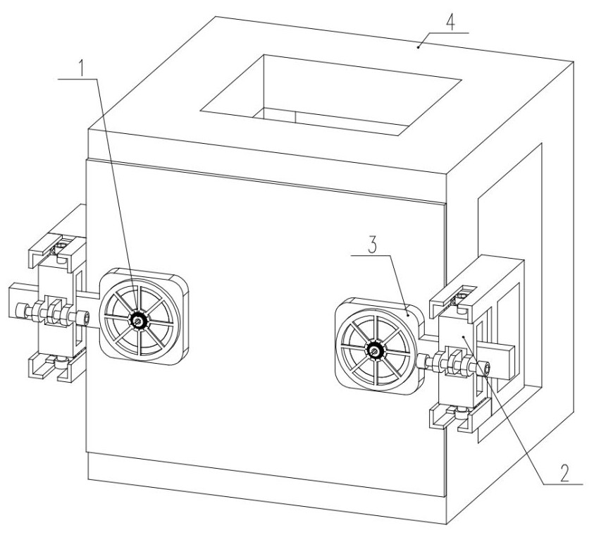
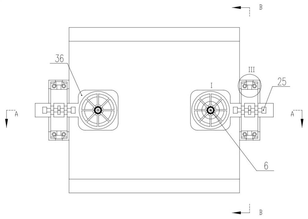
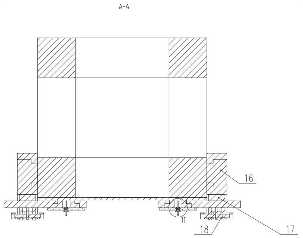
[0009] When the deviation is too large, the position of the iron sheet adsorption magnetic ring fixing frame can be adjusted from the horizontal and vertical directions through the plane adjustment component, so that the annular adjustable strong magnet can bring the iron skin to translate and correct it. The position offset due to thermal stress during the welding process overcomes the technical prejudice that the fixed skin can only be clamped from the opposite direction, and effectively solves the problem that the edge position on the side of the frame cannot be clamped

Method used


Image

  • Clamping device for manual welding of vertical face of electric appliance cabinet and application method of clamping device
  • Clamping device for manual welding of vertical face of electric appliance cabinet and application method of clamping device
  • Clamping device for manual welding of vertical face of electric appliance cabinet and application method of clamping device

Examples


Embodiment Construction

[0044] The technical solutions in the embodiments of the present invention will be clearly and completely described below in conjunction with the accompanying drawings in the embodiments of the present invention. Obviously, the described embodiments are only some of the embodiments of the present invention, not all of them; based on The embodiments of the present invention and all other embodiments obtained by persons of ordinary skill in the art without making creative efforts belong to the protection scope of the present invention.

[0045] In describing the present invention, it should be understood that the terms "upper", "lower", "front", "rear", "left", "right", "top", "bottom", "inner", " "Outside" and other indication orientations or positional relationships are based on the orientations or positional relationships shown in the drawings, and are only for the convenience of describing the present invention and simplifying the description, rather than indicating or implyi...


PUM


Abstract

The invention discloses a clamping device for manual welding of a vertical face of an electric appliance cabinet and an application method of the clamping device. The clamping device comprises a three-dimensional pointer type feedback warning device, a three-axis type two-way fine adjustment reset device, an adjustable ferromagnetic iron sheet adsorption device and a to-be-welded main body rack. The invention belongs to the technical field of welding clamping devices, and particularly relates to the clamping device for manual welding of the vertical face of the electric appliance cabinet and the application method of the clamping device. Through the three-dimensional pointer type feedback warning device, the amplitude and the direction of position deviation generated by the tip, making contact with an iron skin, of a pointer body are fed back, observation by operators is facilitated, and deviation correction measures can be conveniently taken in time when the deviation amplitude is too large; and an annular adjustable strong magnet drives the iron skin to translate, so that the position deviation of the iron skin caused by thermal stress in the welding process is corrected, the technical prejudice that the skin can only be clamped and fixed in the opposite direction is overcome, and the problem that the edge closing position of the side face of the rack cannot be clamped and positioned is effectively solved.

Description

technical field [0001] The invention belongs to the technical field of welding clamping devices, and specifically refers to a clamping device for manual welding of electric cabinet facades and a method for using the same. Background technique [0002] The electrical cabinet is used to place and protect the main switch, the main controller and other electrical control components. Generally, the iron skin is welded on the outside of the frame welded by Fangtong, and it is treated with anti-rust spraying. [0003] The steel frame and the iron skin are separated before spot welding. Since the skin is located on the side of the frame, there is no place for fixing the skin on the frame. In order to position it before welding, it is common to There are two ways of welding positioning: [0004] A: Lay the rack on its side so that the skin is laid on the top of the rack. This welding method can eliminate the adverse effect of gravity on welding, but it is not suitable for racks that...

Claims


Application Information

Patent Timeline
Patent Type & Authority Applications(China)
IPC IPC(8): B23K37/04B23K31/02
CPCB23K37/0443B23K31/02
Inventor 吴长亮
Owner 江苏楚亚电气科技有限公司
Why Eureka
Try Eureka