Fast wall compensation method for mimo through-wall radar imaging

A technology of through-the-wall radar and compensation method, which is applied in the direction of using re-radiation, reflection/re-radiation of radio waves, instruments, etc., can solve problems such as large amount of calculation, achieve large focusing imaging area, correct position deviation, and good application Foreground effect

Active Publication Date: 2022-02-08
CHENGDU UNIVERSITY OF TECHNOLOGY
View PDF0 Cites 0 Cited by
  • Summary
  • Abstract
  • Description
  • Claims
  • Application Information

AI Technical Summary

Problems solved by technology

[0004] The purpose of the present invention is to provide a solution to the above problems, using the method of solving and calculating the abscissa to obtain the propagation delay, overcoming the problem of excessive calculation caused by iteration and traversal in the traditional wall compensation method, and realizing effective wall compensation. , a fast wall compensation method suitable for MIMO through-wall radar imaging with real-time processing

Method used


Image

  • Fast wall compensation method for mimo through-wall radar imaging
  • Fast wall compensation method for mimo through-wall radar imaging
  • Fast wall compensation method for mimo through-wall radar imaging

Examples


Embodiment 1

[0051] Embodiment 1: see Figure 1 to Figure 4 , a fast wall compensation method suitable for MIMO through-wall radar imaging, including the following steps:

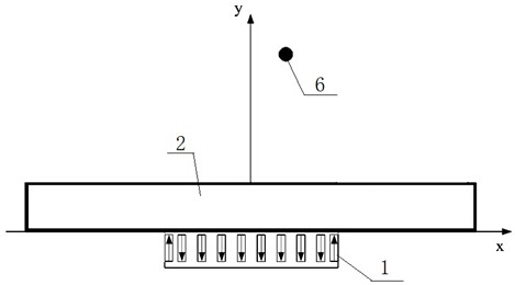
[0052] (1) A MIMO through-the-wall radar 2 with a probe facing the other side of the wall 1 is arranged close to the wall 1 on one side of the wall 1. The total number of transmitting and receiving channels of the MIMO through-the-wall radar 2 is N, and the MIMO through-the-wall radar is installed on the wall 1 One side of 2 is the setting surface, and the other side is the interface;

[0053] (2) Establish a coordinate system with the center point of one side of the MIMO through-the-wall radar 2 close to the wall 1 as the origin, select a rectangular imaging area within the detection range of the MIMO through-the-wall radar 2, and in the rectangular imaging area according to the horizontal and vertical coordinates, etc. The spacing specifies the pixel points;

[0054] (3) MIMO through-the-wall radar 2 performs multi-...

Embodiment 2

[0099] Example 2: see Figure 5 to Figure 7 , in order to better illustrate the present invention, the embodiment 2 uses MATLAB to conduct simulation experiments.

[0100] (1) Set in MATLAB as Figure 5 In the simulation scenario shown, a uniform and stable building wall 1 has a thickness of 35cm and a relative permittivity of 9. One side of the wall 1 is close to the wall 1 and a probe is arranged to face the MIMO through-wall on the other side of the wall 1. Radar 2, MIMO The MIMO array in the MIMO through-wall radar 2 consists of two transmitting antennas and eight receiving antennas. The distance between adjacent transmitting and receiving antennas is 7.5cm, and the distance between adjacent receiving antennas is 15cm.

[0101] (2) The center of the transceiver antenna is the center of the MIMO array, and the center of the MIMO array is located at (0m, 0m), and three small balls are placed in the radar detection area as stationary targets, stationary target 13, stationary...


PUM


Abstract

The invention discloses a fast wall compensation method suitable for MIMO through-wall radar imaging, which comprises the following steps: setting the radar to establish a coordinate system, and specifying pixel points; the MIMO through-wall radar performs multi-transmit and multi-receive real-aperture face-on detection to obtain echoes Signal; find the upper end and lower end corresponding to the first pixel point to calculate the abscissa, calculate the propagation delay value of the first pixel point corresponding to all the transceiver channels, and finally get the propagation delay value of all the pixel points corresponding to all the transceiver channels; combined with the echo signal and propagation delay values ​​according to backprojection imaging to form the final image. The present invention avoids the problem of excessive computational load caused by iteration and traversal in the traditional wall compensation method, and at the same time has the good characteristics of correcting the position deviation of the target image and having a large focused imaging area, and the finally obtained output image can be used for positioning , identifying and extracting targets, and has a good application prospect in MIMO through-wall radar imaging applications that require real-time processing.

Description

technical field [0001] The invention relates to a radar imaging detection method, in particular to a fast wall compensation method suitable for MIMO through-wall radar imaging. Background technique [0002] In the application of detecting the interior of buildings based on MIMO (Multiple Input Multiple Output) through-wall radar, it is a basic detection requirement to locate, identify and extract targets through imaging. Since the electromagnetic parameters (mainly referring to the dielectric constant) of the building wall larger than the free space will cause the electromagnetic wave velocity in the wall to decrease, thereby increasing the propagation delay of the electromagnetic wave between the antenna and the target, and the change of the electromagnetic wave velocity is accompanied by the phenomenon of refraction. , it will make it difficult to estimate the actual propagation delay of electromagnetic waves quickly and accurately. If the influence of wall penetration is ...

Claims


Application Information

Patent Timeline
Patent Type & Authority Patents(China)
IPC IPC(8): G01S13/88G01S13/90G01S7/41
CPCG01S7/418G01S13/888G01S13/904G01S13/9094
Inventor 贾勇陈胜亿晏超郭勇钟晓玲
Owner CHENGDU UNIVERSITY OF TECHNOLOGY
Why Eureka
Try Eureka