X-ray photography device

A photography device, X-ray technology, applied in the directions of projection reproduction, instruments used for radiological diagnosis, image enhancement, etc., to achieve the effect of correcting position offset

Active Publication Date: 2014-10-01
TOSHIBA MEDICAL SYST CORP
View PDF7 Cites 0 Cited by
  • Summary
  • Abstract
  • Description
  • Claims
  • Application Information

AI Technical Summary

Problems solved by technology

X-ray image collection department collects X-ray images

Method used


Image

  • X-ray photography device
  • X-ray photography device
  • X-ray photography device

Examples


Embodiment Construction

[0025] Embodiments of the X-ray imaging apparatus will be described in detail below with reference to the drawings.

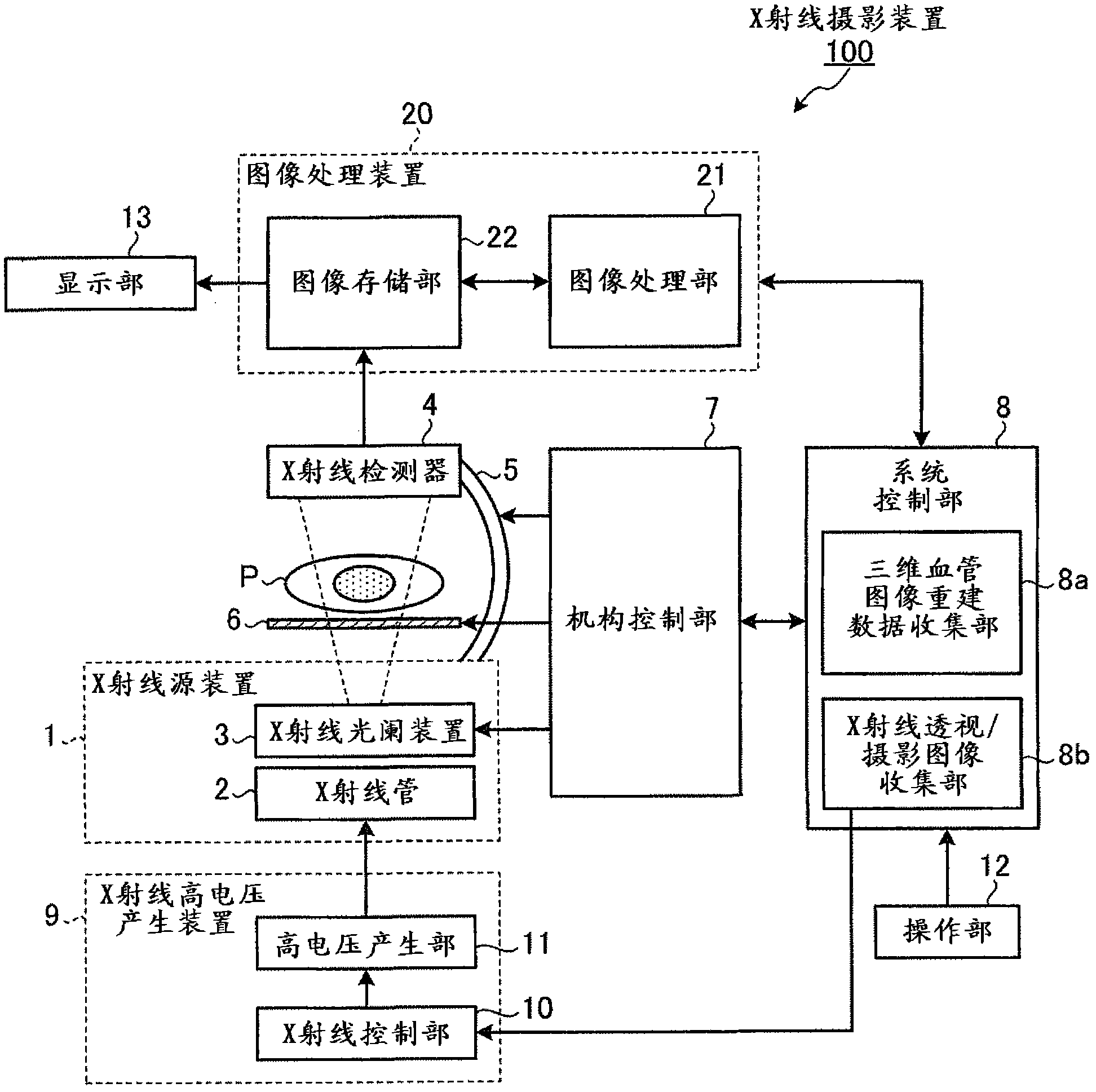
[0026] First, use figure 1 , the outline of the X-ray imaging apparatus related to the first embodiment will be described. figure 1 It is a figure for demonstrating the outline|summary of the X-ray imaging apparatus related to Example 1.

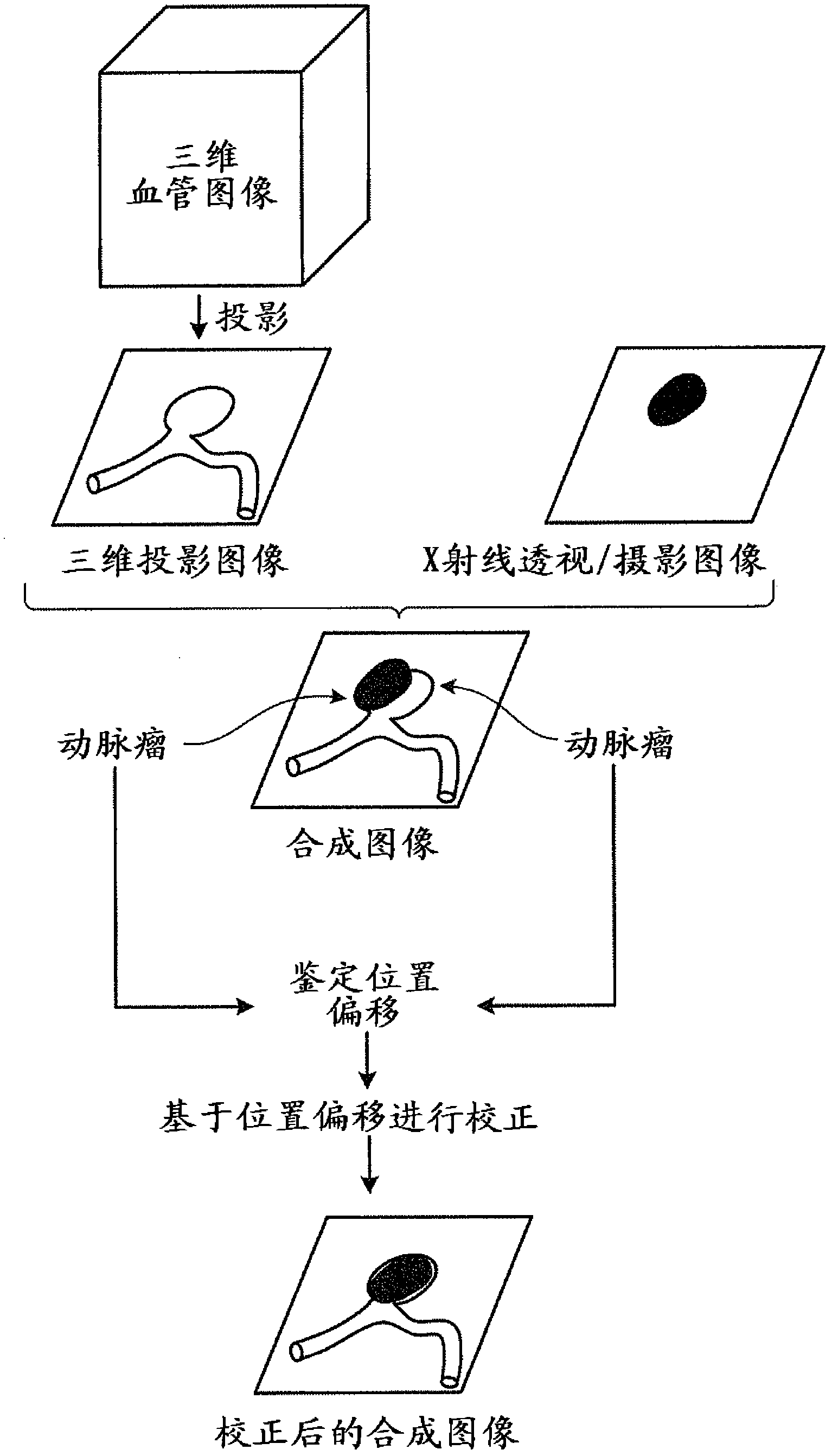
[0027] Such as figure 1 As shown, the X-ray imaging apparatus related to Example 1 acquires a three-dimensional blood vessel image emphasizing blood vessel images. In addition, the X-ray imaging device collects X-ray fluoroscopic images.

[0028] Next, the X-ray imaging device generates a three-dimensional projection image projected based on the condition of the X-ray imaging device based on the collected three-dimensional blood vessel image, and generates a composite image of the generated three-dimensional projection image and the X-ray fluoroscopic image.

[0029] Then, the X-ray imaging device identifies a positional ...


PUM


Abstract

The present invention relates to an X-ray imaging apparatus in which a three-dimensional blood vessel image collecting unit collects three-dimensional blood vessel images. In addition, the X-ray image collection unit collects X-ray images. Then, the composite image generator generates a three-dimensional projection image projected based on the state of the X-ray imaging device based on the collected three-dimensional blood vessel image, and generates a composite image of the generated three-dimensional projection image and the X-ray image. Next, the positional displacement identification unit identifies a positional deviation between the aneurysm on the three-dimensional projection image and the aneurysm on the X-ray image. Then, the display control unit performs control to correct the composite image using the identified positional shift, and displays the corrected composite image on the display unit.

Description

[0001] Cross References to Related Applications [0002] This application is based on and claims priority from prior Japanese Patent Application No. 2009-249456 filed on October 29, 2009 and prior Japanese Patent Application No. 2010-222249 filed on September 30, 2010, all of which The contents are incorporated by reference in this application. technical field [0003] The present invention relates to X-ray imaging devices. Background technique [0004] In interventional therapy, which is one of the treatment methods for aneurysms, a doctor inserts a catheter or a guide wire while observing an X-ray fluoroscopic image displayed on a monitor. . However, it is difficult to identify blood vessels on X-ray images without the injection of contrast agent. On the other hand, if the contrast agent is continuously injected, the load on the patient will increase. Therefore, conventionally, a road map function has been used to display on a monitor a composite image of an image take...

Claims


Application Information

Patent Timeline
Patent Type & Authority Patents(China)
IPC IPC(8): A61B6/00
CPCA61B6/463A61B6/481G06T2207/10121A61B6/563G06T11/006A61B5/055G06T2207/10072A61B6/504A61B6/5235A61B6/466A61B5/0002G06T7/0026G06T2211/404G06T2207/30101G06T19/003G06T7/32
Inventor 大石悟
Owner TOSHIBA MEDICAL SYST CORP
Why Eureka
Try Eureka