Optical axis adjusting apparatus, optical axis adjusting method, and projection type display apparatus

A display device and optical axis technology, applied in projection devices, optics, optical components, etc., can solve problems such as relying on technical capabilities and difficult laser offset adjustment

Inactive Publication Date: 2013-11-06
HITACHI LTD
View PDF2 Cites 0 Cited by
  • Summary
  • Abstract
  • Description
  • Claims
  • Application Information

AI Technical Summary

Problems solved by technology

[0008] The conventional projection display device disclosed in Patent Document 2 adjusts the offset of each laser beam using a MEMS mirror while projecting each laser beam onto a screen while viewing the screen. technical capabilities, and in addition, it is difficult to perform precise laser offset adjustments over the entire irradiation area

Method used


Image

  • Optical axis adjusting apparatus, optical axis adjusting method, and projection type display apparatus
  • Optical axis adjusting apparatus, optical axis adjusting method, and projection type display apparatus
  • Optical axis adjusting apparatus, optical axis adjusting method, and projection type display apparatus

Examples


Embodiment approach 1

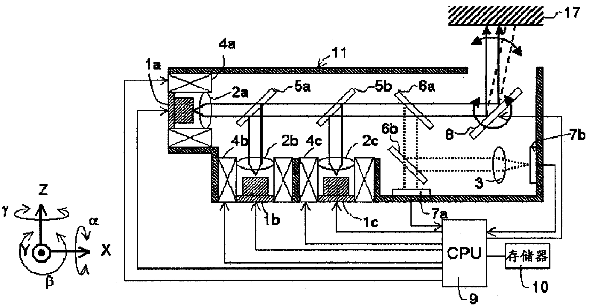
[0028] figure 1 It is a figure explaining the basic structure of the projection display apparatus concerning 1st Embodiment of this invention. exist figure 1 Among them, reference numerals 1a, 1b, 1c respectively represent light sources such as green, blue, and red semiconductor lasers; reference numerals 2a, 2b, 2c represent light sources 1a, 1b, and 1c condenser lenses; reference numeral 3 represents condenser lenses. Optical lens; Reference numerals 4a, 4b, 4c represent actuators for light sources and condenser lenses; Reference numerals 5a, 5b represent light-combining filters that combine light beam lines from each light source; Reference numerals 6a and 6b denote optical filters for reflecting and splitting part of the combined laser light; reference numeral 7a denotes a camera mechanism for position detection; reference numeral 7b denotes a camera mechanism for angle detection; A scanning mirror for projecting an image onto a screen 17 by reflecting light beams at an ...

Embodiment approach 2

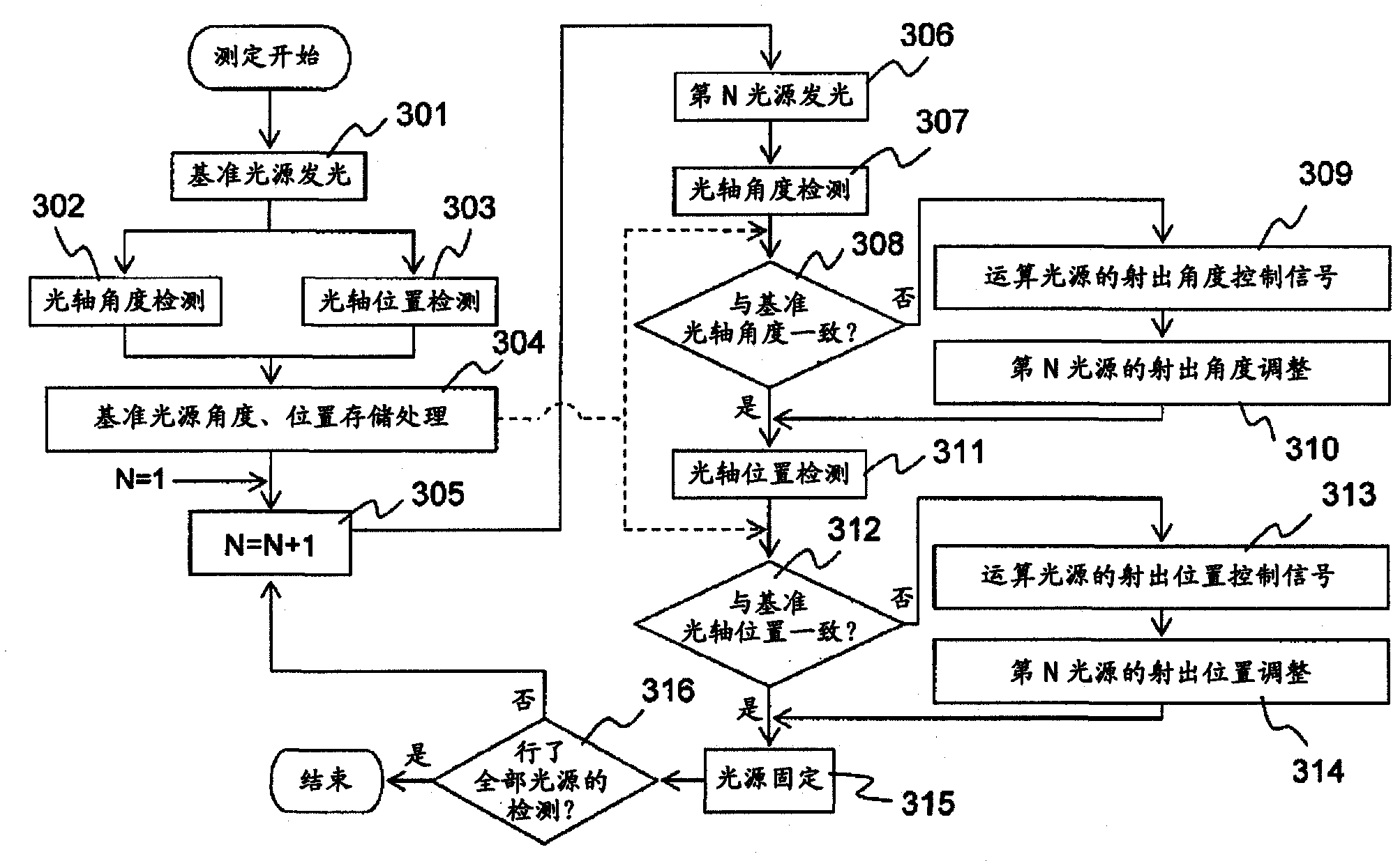
[0048] image 3 It is a flowchart explaining the method of adjusting the optical axis of the light sources 1a, 1b, 1c which is the second embodiment of the present invention, and it will be described below. The optical axis adjustment method of the second embodiment is different from that of the first embodiment in the optical axis adjustment step, and the basic configuration of the display device is the same as that of the first embodiment. figure 1 The same as shown and explained.

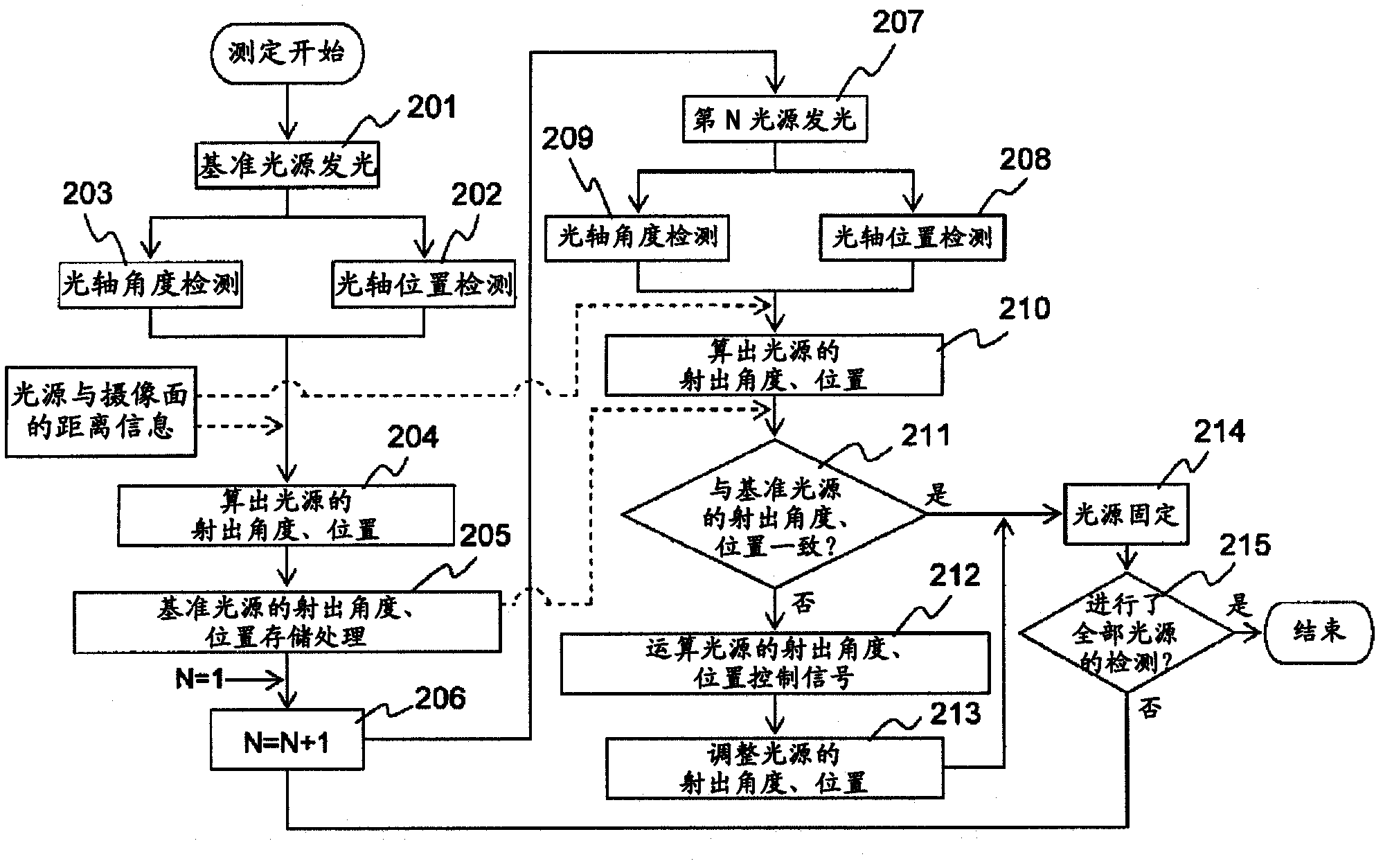
[0049] (1) First, as in the case of the first embodiment, the light source 1a is selected as a reference light source, only the reference light source 1a is turned on, and the laser light emitted from the light source 1a is reflected and spectroscopically split by a filter 6a, 6b are divided into two laser beams, the light that has passed through the optical filter 6b is incident on the imaging surface of the position detection imaging mechanism 7a, and the light reflected by the optical filter ...

Embodiment approach 3

[0060] Figure 4 is a diagram illustrating the basic configuration of a projection display device according to a third embodiment of the present invention, Figure 5 It is a diagram explaining the inclination of the light source 1 placed at the focal position of the condenser lens 2 and the position change of the optical axis 16 of the laser light emitted from the condenser lens 2 . Figure 4 A third embodiment of the invention is shown with figure 1 The configurations of the first and second embodiments of the present invention shown and described are basically the same configuration, and the method of adjusting the optical axis is also the same.

[0061] The third embodiment of the present invention and figure 1 The difference between the first embodiment of the present invention shown and described lies in the optical axis adjustment actuators of the light sources 1a, 1b, 1c and the adjustment method of the actuators. Hereinafter, differences between the third embodiment...


PUM


Abstract

A projection type display apparatus in which an inclination and a positional deviation of optical axes among a plurality of light sources can be easily corrected to obtain a high quality projection image. Green, blue and red laser beams emitted from light sources are converted into collimated beams by condenser lenses, and the positions and angles of the optical axes of the beams of the three colors are evaluated by position detection imaging device and angle detection imaging device, respectively. The positions and angles of the light sources are adjusted by respective actuators so that the positions and angles of the optical axes match each other. Consequently, the laser beams emitted from the light sources can be combined with high accuracy to thereby realize a high definition projection type display apparatus.

Description

technical field [0001] The present invention relates to an optical axis adjustment device, an optical axis adjustment method, and a projection display device, and more particularly, to an optical axis adjustment device and an optical axis adjustment method for aligning the optical axes of multiple laser beams, such as a laser projection display device, with high precision. And a projection display device using the optical axis adjustment device. Background technique [0002] In recent years, along with the development of small green lasers and blue semiconductor lasers using wavelength conversion elements, ultra-small projectors using laser light as a light source have been proposed. A projector using such a laser light source has good color reproducibility, can realize low power consumption, miniaturization, and is a scanning image display device, so the pixels are not fixed, and the resolution can be easily converted. Such advantages. [0003] In addition, ultra-small pr...

Claims


Application Information

Patent Timeline
Patent Type & Authority Patents(China)
IPC IPC(8): G02B27/62G02B26/10G03B21/00H04N5/74
CPCH04N9/3155G03B21/28H04N9/3135G03B21/00G03B21/14H04N9/3129G03B21/2046G03B21/2013G03B21/2033G03B21/2066G02B27/62G02B26/10H04N5/74
Inventor 桥爪滋郎
Owner HITACHI LTD
Why Eureka
Try Eureka