Optical axis adjusting apparatus, optical axis adjusting method, and projection type display apparatus
A technology for a display device and an adjustment device, which is applied to projection devices, optics, optical components, etc., can solve the problems of difficult laser offset adjustment, dependence on technical capabilities, etc.
- Summary
- Abstract
- Description
- Claims
- Application Information
AI Technical Summary
Problems solved by technology
Method used
Image
Examples
Embodiment approach 1
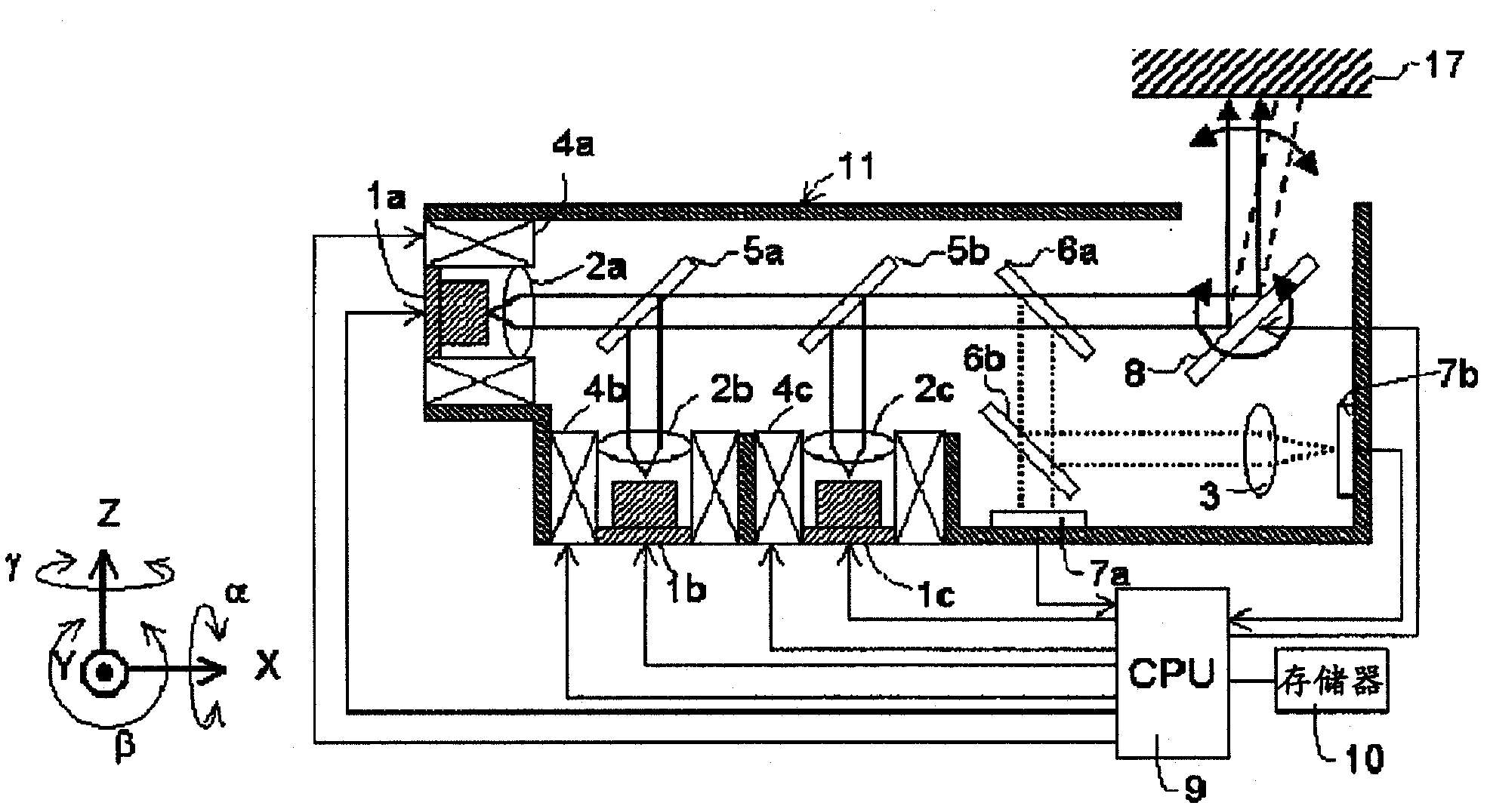
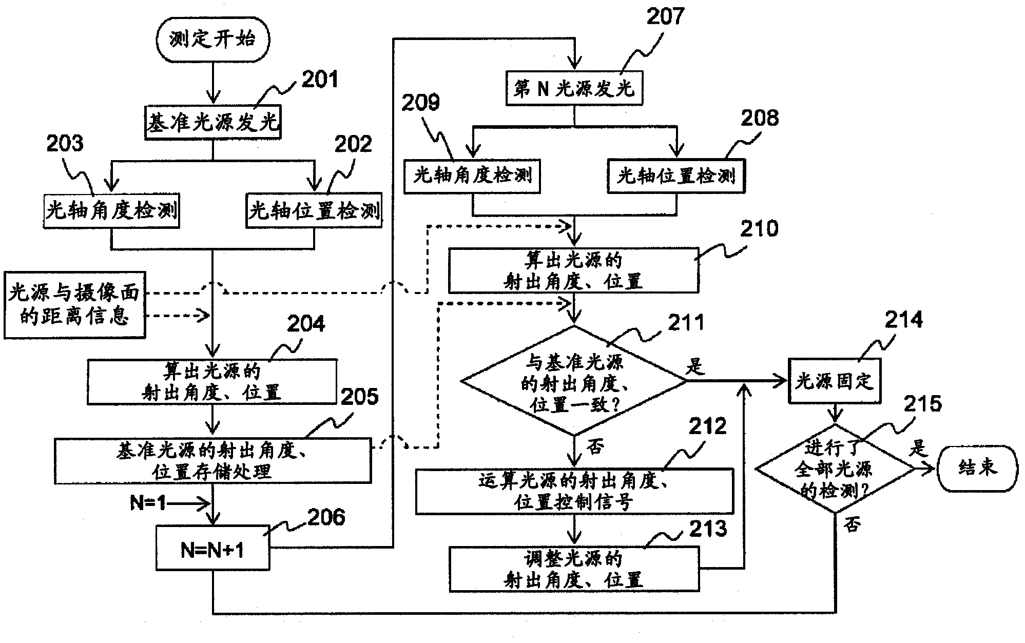
[0028] figure 1 It is a figure explaining the basic structure of the projection display apparatus concerning 1st Embodiment of this invention. exist figure 1 Among them, reference numerals 1a, 1b, 1c respectively represent light sources such as green, blue, and red semiconductor lasers; reference numerals 2a, 2b, 2c represent light sources 1a, 1b, and 1c condenser lenses; reference numeral 3 represents condenser lenses. Optical lens; Reference numerals 4a, 4b, 4c represent actuators for light sources and condenser lenses; Reference numerals 5a, 5b represent light-combining filters that combine light beam lines from each light source; Reference numerals 6a and 6b denote optical filters for reflecting and splitting part of the combined laser light; reference numeral 7a denotes a camera mechanism for position detection; reference numeral 7b denotes a camera mechanism for angle detection; A scanning mirror for projecting an image onto a screen 17 by reflecting light beams at an ...
Embodiment approach 2
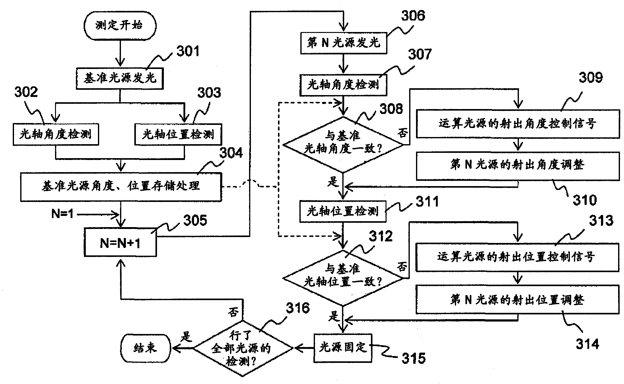
[0048] image 3 It is a flowchart explaining the method of adjusting the optical axis of the light sources 1a, 1b, 1c which is the second embodiment of the present invention, and it will be described below. The optical axis adjustment method of the second embodiment is different from that of the first embodiment in the optical axis adjustment step, and the basic configuration of the display device is the same as that of the first embodiment. figure 1 The same as shown and explained.
[0049] (1) First, as in the case of the first embodiment, the light source 1a is selected as a reference light source, only the reference light source 1a is turned on, and the laser light emitted from the light source 1a is reflected and spectroscopically split by a filter 6a, 6b are divided into two laser beams, the light that has passed through the optical filter 6b is incident on the imaging surface of the position detection imaging mechanism 7a, and the light reflected by the optical filter ...
Embodiment approach 3
[0060] Figure 4 is a diagram illustrating the basic configuration of a projection display device according to a third embodiment of the present invention, Figure 5 It is a diagram explaining the inclination of the light source 1 placed at the focal position of the condenser lens 2 and the position change of the optical axis 16 of the laser light emitted from the condenser lens 2 . Figure 4 A third embodiment of the invention is shown with figure 1 The configurations of the first and second embodiments of the present invention shown and described are basically the same configuration, and the method of adjusting the optical axis is also the same.
[0061] The third embodiment of the present invention and figure 1 The difference between the first embodiment of the present invention shown and described lies in the optical axis adjustment actuators of the light sources 1a, 1b, 1c and the adjustment method of the actuators. Hereinafter, differences between the third embodiment...
PUM
 Abstract
Description
Claims
Application Information
 - R&D
- Intellectual Property
- Life Sciences
- Materials
- Tech Scout
- Unparalleled Data Quality
- Higher Quality Content
- 60% Fewer Hallucinations
Browse by: Latest US Patents, China's latest patents, Technical Efficacy Thesaurus, Application Domain, Technology Topic, Popular Technical Reports.
© 2025 PatSnap. All rights reserved.Legal|Privacy policy|Modern Slavery Act Transparency Statement|Sitemap|About US| Contact US: help@patsnap.com


