Edge milling machine

An edge milling machine and host technology, applied in milling machine equipment, milling machine equipment details, metal processing machinery parts, etc., can solve the problems of poor workpiece clamping rigidity, low precision of dovetail guides, affecting milling accuracy, etc., and achieve workpiece clamping rigidity. Good, good heat dissipation and chip removal effect, simplified design and production effect

Inactive Publication Date: 2010-06-30
王及元
View PDF0 Cites 10 Cited by
  • Summary
  • Abstract
  • Description
  • Claims
  • Application Information

AI Technical Summary

Problems solved by technology

[0002] The main engine of the existing edge milling machine adopts ordinary reducer and self-made transmission box, which is difficult, poor in precision and short in service life
The guide rail adopts dovetail guide rail with low precision and short service life. When working, the milling cutter does not move, the workpiece (steel plate) moves, and the clamping rigidity of the workpiece is poor, which affects the milling accuracy; the diameter of the cutter head is generally below 600mm, and the work efficiency is low.

Method used


Image

  • Edge milling machine
  • Edge milling machine

Examples


Embodiment Construction

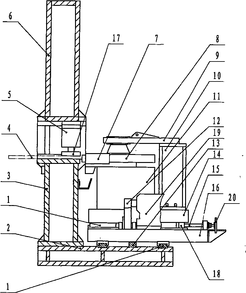
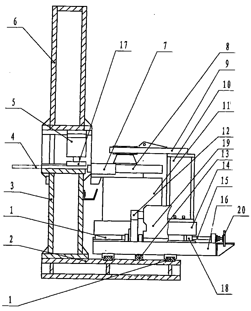
[0008] Referring to the drawings, it includes a bed 3, the bed is fixed on the base 2, the upper beam 6 is fixed on the bed 3 through the connecting beam, and 12 oil cylinders 5 of its clamping structure are evenly fixed on the upper beam 6, and the oil cylinders 5. There is a plywood presser foot 17 below; the main machine 11 is fixed on the horizontal support plate 14, and the main shaft of the main machine is equipped with a cutter head 8; the lower part of the vertical support plate 16 of the cutter mechanism is fixed on the slider of the lower slider guide rail assembly 1, and the slider The guide rail of the guide rail assembly 1 is fixed on the base 2; the motor reducer 19 of the cutting mechanism is fixed on the vertical support plate 16, and the motor reducer 19 is equipped with a gear 12, which meshes with the rack 13, and the rack 13 is fixed to the base 2, the screw nut 18 of the feed mechanism is fixed on the horizontal support plate 14, the screw 15 is screwed on ...


PUM


Abstract

The invention provides an edge milling machine, which relates to an edge milling device for steel plates and is mainly designed for solving the problems of low edge milling precision and short service life of the prior edge milling machine. The edge milling device comprises a lathe bed, a base and an upper beam, wherein an oil cylinder is fixed on the upper beam, and clamp plate presser pins are arranged under the oil cylinder; a main machine is fixed on a transverse supporting plate, and a main shaft thereof is provided with a cutterhead; the lower part of a longitudinal supporting plate is fixed on a slide block guideway component on a lower layer, and the slide block guideway component is fixed on the base; an electric machine speed reducer is fixed on the longitudinal supporting plate, gear wheels on the electric machine speed reducer are meshed with rackbars, screws are fixed on a horizontal supporting plate, and a screw rod is screwed in the screw; the end of the screw rod is provided with a handwheel, and slide block guideway components on upper layers are fixed on the horizontal supporting plate and the longitudinal supporting plate; the outer end of the main shaft of the main machine is fixed on the horizontal supporting plate by a shaft, a support frame and a support seat; the diameter of the cutterhead is 1000 mm, the main machine adopts the speed reducer with curved tooth bevel gears and hard tooth surfaces, and the slide block guideway components adopt linear rolling guideways. The edge milling device has the advantages of high milling precision and long service life.

Description

Technical field: [0001] The invention relates to a device for edge milling of steel plates used for producing steel pipes. Background technique: [0002] The main machine of the existing edge milling machine adopts an ordinary reducer and makes a transmission box by itself, which is difficult, has poor precision and has a short service life. The guide rail adopts dovetail guide rail with low precision and short service life. The milling cutter does not move during operation, the workpiece (steel plate) moves, and the workpiece clamping rigidity is poor, which affects the milling accuracy; the diameter of the cutter head is generally below 600mm, and the work efficiency is low. Invention content: [0003] The technical problem to be solved by the present invention is to provide an edge milling machine with high edge milling precision and long service life. [0004] The purpose of the present invention is achieved in this way: it includes a bed, the bed is fixed on the base...

Claims


Application Information

Patent Timeline
Patent Type & Authority Applications(China)
IPC IPC(8): B23C3/12B23Q1/01B23Q5/34
Inventor 王及元
Owner 王及元
Why Eureka
Try Eureka