
High-temperature slag handling technology by tilting roller process and device

A treatment device and drum method technology, applied in the field of high-temperature slag treatment, can solve problems such as poor feeding, complex structure, deposition, etc., and achieve stable performance and uniform particle size

Active Publication Date: 2011-06-15
BAOSHAN IRON & STEEL CO LTD
View PDF1 Cites 0 Cited by
  • Summary
  • Abstract
  • Description
  • Claims
  • Application Information

AI Technical Summary

Problems solved by technology

The disadvantages of the horizontal axis drum device are: the fixed body at one end of the drum is directly in contact with the high-temperature slag and the cooling medium, the lateral force is large, the high-temperature wear is serious, the structure is complicated, and the cost and maintenance cost are high; The effective flow area and inclination angle of the feed chute are small, and the high-viscosity slag is easy to adhere to the chute wall, causing blockage and poor feeding; the horizontal section of the exhaust port is long, and the internal deposition and slagging are serious
The disadvantage is that the side lining plate of the inner cylinder is worn by the high temperature of the cooling body and steel slag, and the service life is short; the treated steel slag and turbid circulating water are discharged from the discharge chute at the same time, and enter the subsequent scale conveyor together. The slag-water separation is carried out on the conveyor, which not only increases the load of the scale plate conveyor, but also easily washes down a large amount of fine-grained steel slag and mixes it into the circulating water, which increases the load of the subsequent water treatment process

Method used


Image

  • High-temperature slag handling technology by tilting roller process and device
  • High-temperature slag handling technology by tilting roller process and device
  • High-temperature slag handling technology by tilting roller process and device

Examples


Embodiment Construction

[0029] The present invention will be further described below in conjunction with the accompanying drawings and specific embodiments.

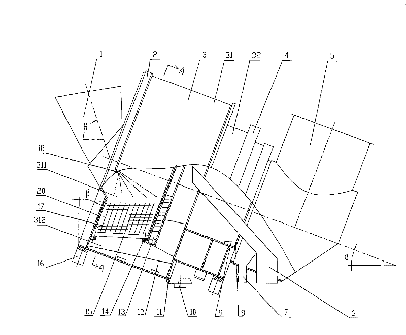
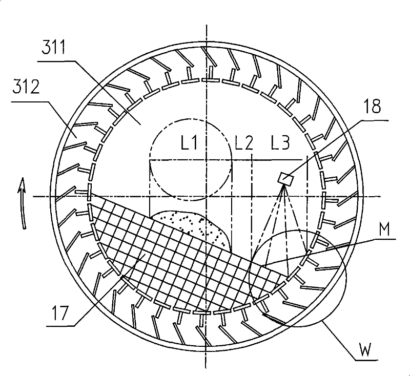
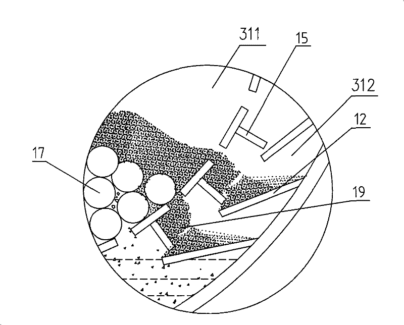
[0030] see figure 1 , an inclined drum method high-temperature slag treatment device, including a feed hopper 1, a drum device, a thrust device 10, a discharge chute 6, and a gas collection and discharge device 5. The drum device includes a working cylinder 3 composed of a front cylinder 31 and a rear cylinder 32, a nozzle 18 installed in the front cylinder 31, a device for supporting and driving the working cylinder. The front cylinder 31 is composed of an inner cylinder 311 and an outer cylinder 312. The inner cylinder 311 is composed of an end cover 20, an end motherboard 135, a liner 131, and several grate bars 15; the outer cylinder 312 is set inside The outside of the cylinder 311 is fixed by rigid parts, and the inner surface of the outer cylinder 312 is equipped with a plurality of evenly distributed cylinder lifting plates 12 with dra...


PUM


Abstract

The invention discloses a high-temperature slag handling technology by the tilting roller process and a high-temperature slag handling device. The handling technology includes that high-temperature metallurgical slag is poured into a rotating working barrel body with a certain angle of inclination in the axial direction by a loading hopper; the slag in a front barrel body of the working barrel body is fast cooled by a cooling medium and the cooling water sprayed by a spray head in sequence and then crushed; the cooled and crushed slag particles are driven to drop from the gaps among cage barsand the gaps between the cage bars and a barrel body shoveling plate into a lower chamber filled with the cooling water to be cooled for the second time; along with the rotation of the working barrelbody, the slag particles soaking in the cooling water in the lower chamber are carried to the upper part of the front barrel body by the barrel body shoveling plate provided with dewatering holes, poured into an open discharging chute and conveyed out of the device; the cooling water that carries fine slag particles and is separated by the barrel body shoveling plate flows to a rear barrel body, and the fine slag particles separated and intercepted by a netty slag-water separating device arranged on the rear barrel body are sent to the discharging chute and conveyed out of the device by a small shoveling plate arranged on the internal side surface of the rear barrel body.

Description

technical field [0001] The invention relates to a high-temperature slag treatment technology, in particular to a drum method high-temperature slag treatment process and device. Background technique [0002] The drum method steel slag treatment technology is a closed, rapid and resource-based new technology for thermal treatment of steel slag. It realizes the dynamic, continuous and rapid cooling of high-temperature metallurgical slag in a closed container and crushes it into granular products less than 100 °C. The function of slag, and the dusty steam generated in the process is discharged from the chimney after purification, eliminating the pollution scene of steam and dust in the traditional slag treatment process. This process not only has a short process and low investment, but also is easy to operate, safe and reliable, and the treated slag can be used directly, which meets the environmental protection requirements in the new situation and has been developed rapidly. ...

Claims


Application Information

Patent Timeline
Patent Type & Authority Patents(China)
IPC IPC(8): C21B3/06C04B5/00
CPCY02W30/50
Inventor 肖永力李永谦刘茵
Owner BAOSHAN IRON & STEEL CO LTD
Learn More