Distributing head on vehicle-mounted bottle

A technology of dispensing head and vehicle-mounted bottle, applied in the field of vehicle-mounted bottle, can solve problems such as unstable work, influence on engine, engine tremor, etc., achieve stable and reliable operation, ensure air supply, and facilitate replacement.

Inactive Publication Date: 2010-06-30
ZHANGJIAGANG FURUI SPECIAL EQUIP CO LTD
View PDF0 Cites 3 Cited by
  • Summary
  • Abstract
  • Description
  • Claims
  • Application Information

AI Technical Summary

Problems solved by technology

In the above-mentioned liquid supply pipeline, since the one-way valve is arranged in the liquid outlet pipe in the inner tank connected with the above-mentioned liquid inlet pipe, the inner diameter of the liquid outlet pipe is narrow, which hinders the smooth circulation after the one-way valve is opened, affecting to supply air to the engine properly, causing the engine to tremble due to not getting enough fuel, and the operation is not stable; and if the check valve is damaged, it cannot be replaced without cutting and welding

Method used


Image

  • Distributing head on vehicle-mounted bottle
  • Distributing head on vehicle-mounted bottle

Examples


Embodiment Construction

[0009] Specific embodiments of the present invention will be described in detail below in conjunction with the accompanying drawings.

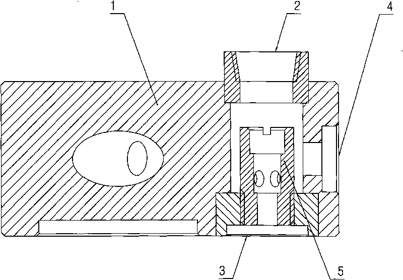
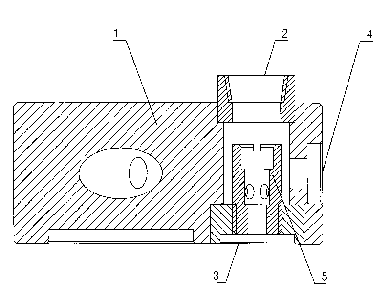
[0010] Such as figure 1 As shown, the dispensing head on the vehicle-mounted bottle of the present invention includes: a distributing head body 1, which is provided with an air inlet 2, a liquid inlet 3 and a gas-liquid output port 4 on one side of the distributing head body 1. A three-way; a one-way valve 5 to prevent backflow is provided at the liquid inlet 3. In this embodiment, the air inlet 2 and the liquid inlet 3 are arranged on the end surfaces of both sides of the distribution head body 1 , and the gas-liquid output port 4 is arranged on the side surfaces of the distribution head body 1 .

[0011] The working principle of the present invention is the same as that described in the background art, and will not be repeated here. But because the present invention is by after the one-way valve is moved in the distributing head, the speed...


PUM


Abstract

The invention discloses a distributing head on a vehicle-mounted bottle, being capable of increasing liquid inlet speed and ensuring the stable work of an engine and comprising a distributing head body. The lateral of one side of the distributing head body is provided with a tee fitting comprising an air inlet, a liquid inlet and an air and liquid delivery outlet, wherein the liquid inlet is provided with a check valve for preventing backflow. In the invention, the liquid inlet speed obtains reliable guarantee after the check valve is shifted into the distributing head, thereby ensuring the liquid supply amount for a vaporizer, also ensuring the air supply amount of the vaporizer for the engine and enabling the engine to stably and reliably work.

Description

technical field [0001] The present invention relates to a vehicle bottle, in particular to a dispensing head on the vehicle bottle. Background technique [0002] The current vehicle-mounted bottle is the dispensing head of the low-temperature insulated gas cylinder for automobiles, including: a distributing head body, and a tee consisting of an air inlet, a liquid inlet and a gas-liquid outlet is arranged on one side of the distributing head. Among them, the air inlet and the liquid inlet are respectively connected to the gas cylinder through the air inlet pipeline and the liquid inlet pipeline, and the air inlet pipeline and the liquid inlet pipeline are respectively provided with an economical valve and a one-way valve; The pipeline is connected with the carburetor, and the carburetor is then connected with the engine through the pipeline. When the pressure in the gas cylinder exceeds the pressure set by the economical valve, the natural gas in the gas cylinder will pass ...

Claims


Application Information

Patent Timeline
Patent Type & Authority Applications(China)
IPC IPC(8): F17C13/00F17C13/04
Inventor 袁卫峰
Owner ZHANGJIAGANG FURUI SPECIAL EQUIP CO LTD
Why Eureka
Try Eureka