
Power supply device and control method and charging method thereof

A technology of a power supply device and a control method, which is applied to circuit devices, measuring devices, emergency power supply arrangements, etc., can solve problems such as failure to meet the requirements of energy-consuming products, failure to meet the specifications of power consumption loss, etc.

Inactive Publication Date: 2010-06-30
LITE ON TECH CHANG ZHOU CO LTD +2
View PDF0 Cites 8 Cited by
  • Summary
  • Abstract
  • Description
  • Claims
  • Application Information

AI Technical Summary

Problems solved by technology

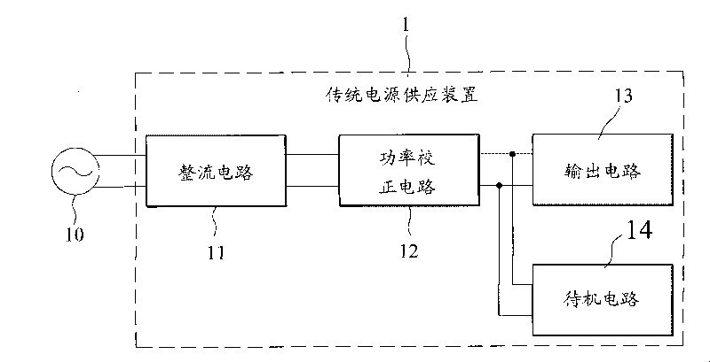
However, with this method, it is impossible to meet the increasingly stringent power consumption regulations
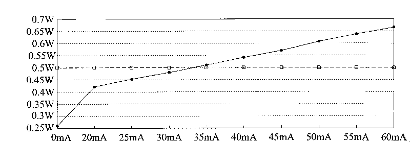
like figure 2 As shown, when operating at 50mA to 60mA, its power consumption is between 0.6W and 0.7W, which cannot meet the requirements of the Environmental Design Directive for Energy-consuming Products in 2013

Method used


Image

  • Power supply device and control method and charging method thereof
  • Power supply device and control method and charging method thereof
  • Power supply device and control method and charging method thereof

Examples


Embodiment Construction

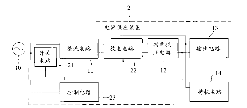
[0019] image 3 Shown is a schematic diagram of system modules of a power supply device according to an embodiment of the present invention.

[0020] The power supply device 2 has a rectifier circuit 11 connected to an external power source 10 through a switch circuit 21 to receive an external power signal from the external power source 10 and perform rectification to form a rectified signal, and the switch circuit 21 is controlled by The control signal of the control circuit 23, in a normal working mode, the switch circuit 21 is turned on so that the external power supply signal is transmitted to the output circuit through the rectifier circuit 11, the discharge circuit 22, and the power factor correction circuit 12, wherein the switch circuit 21 and The discharge circuit 22 can be controlled by the output circuit 13, or it can be controlled by the control circuit; and in a standby mode, the switch circuit 21 is not conducted, so that a first cycle or a second The periodic e...


PUM


Abstract

The invention relates to a power supply device. the power supply device comprises a switch circuit, an output circuit, a standby circuit, a discharging circuit and a control circuit, wherein the output circuit is connected with an external power source through the switch circuit to output a main power supply; the standby circuit is connected with the external power source to output a standby power supply; the discharging circuit is connected between the output circuit and the external power source to generate a discharging path; the control circuit is connected with the external power source, connects the switch circuit according to a normal operation node so that the power supply signal of the external power source can be transmitted to the output circuit, disconnects the switch circuit according to a standby operation node so that the first period or second period of the power supply signal can be transmitted to the standby circuit and connects the discharging circuit when the external power source is removed so that the power supply device can discharge by the discharging circuit.

Description

technical field [0001] The invention relates to a power supply device, especially a control method and a discharge method of the power supply in a standby operation state. Background technique [0002] The advancement of science and technology has provided many electronic devices with different functions in the life of modern people, which is convenient for people to enjoy and also accelerates the dissemination of people's various information, such as: TV, computer, workstation, network domain, etc., relatively also need Provide larger and more stable power support. Used for work, games, communication or information processing, etc., almost completely rely on computer equipment for processing. Therefore, computer equipment must be able to provide stable operation to facilitate people's use. At present, general computer equipment generally includes a central processing unit (Central Processing Unit, CPU), a chipset, a memory, a storage device, an interface connection device...

Claims


Application Information

Patent Timeline
Patent Type & Authority Applications(China)
IPC IPC(8): G06F1/26H02M7/217
CPCH02M7/06Y02B70/16H02M2001/0032G06F1/32H02J9/005H02M1/0032Y02B70/10Y02B70/30Y04S20/20
Inventor 余伟诚许昀杰
Owner LITE ON TECH CHANG ZHOU CO LTD
Learn More