Laser cutting method

A cutting method, laser technology, applied in the direction of sustainable manufacturing/processing, final product manufacturing, manufacturing tools, etc.

Inactive Publication Date: 2010-06-30
CONTREL TECH CO LTD
View PDF1 Cites 3 Cited by
  • Summary
  • Abstract
  • Description
  • Claims
  • Application Information

AI Technical Summary

Problems solved by technology

Although it has improved the defect of pre-marking in the aforementioned existing process, the first line segment cut by the laser device is still used for correction purposes, so it is similar to the pre-marking technology in the existing process, so there is still improvement Space

Method used


Image

  • Laser cutting method
  • Laser cutting method
  • Laser cutting method

Examples


Embodiment Construction

[0015] In order to describe in detail the features and effects of the present invention, the following preferred embodiments are given below and are described in conjunction with the drawings, wherein:

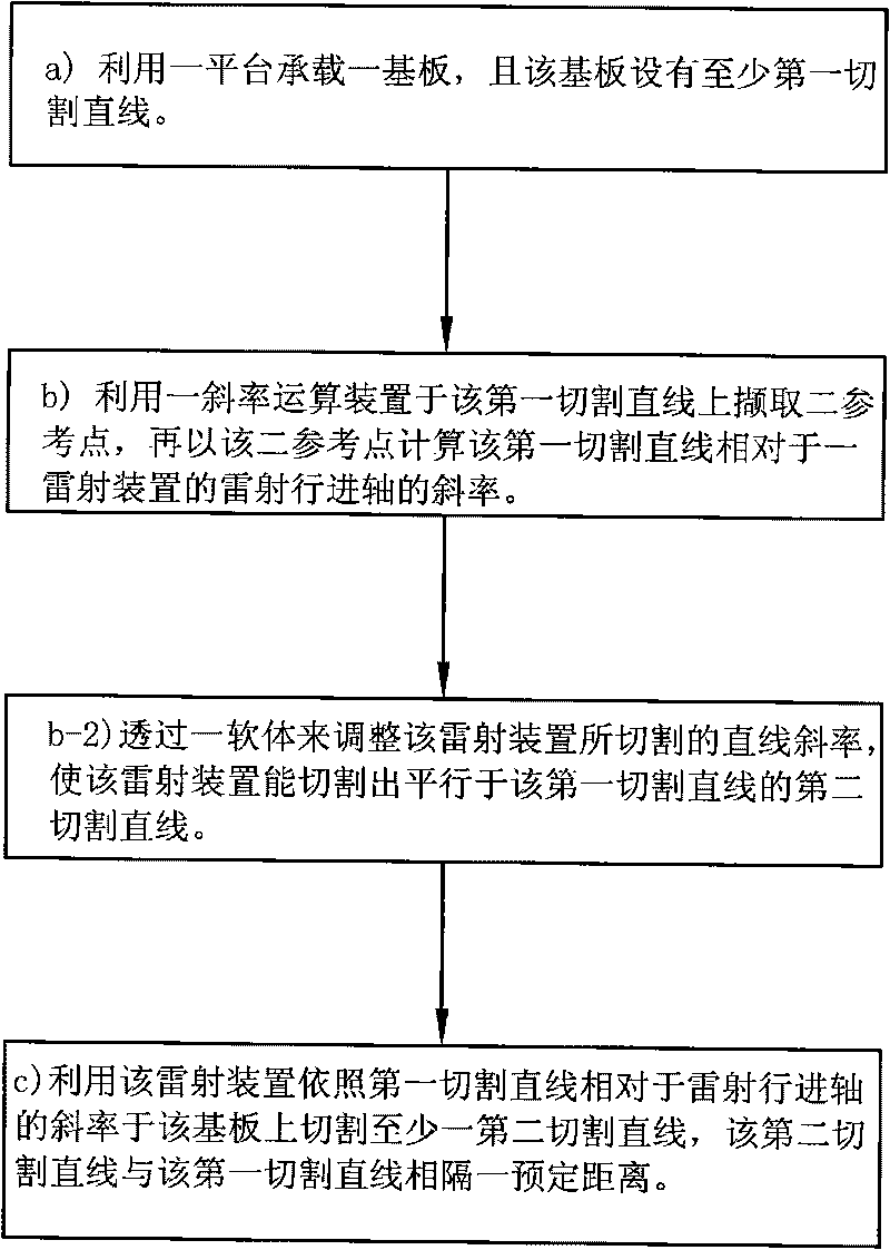
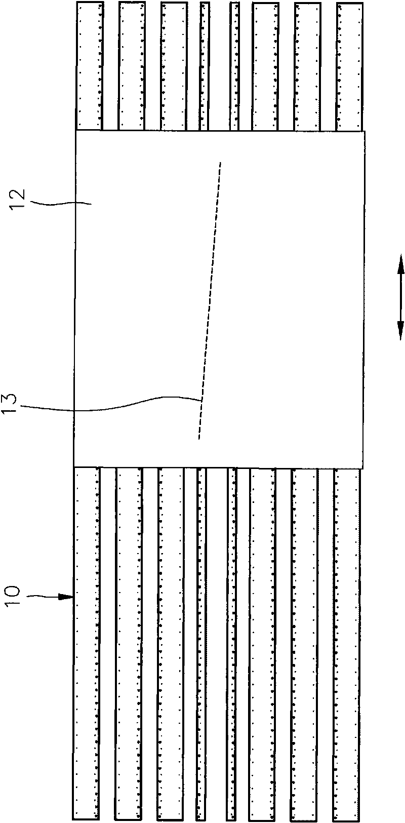
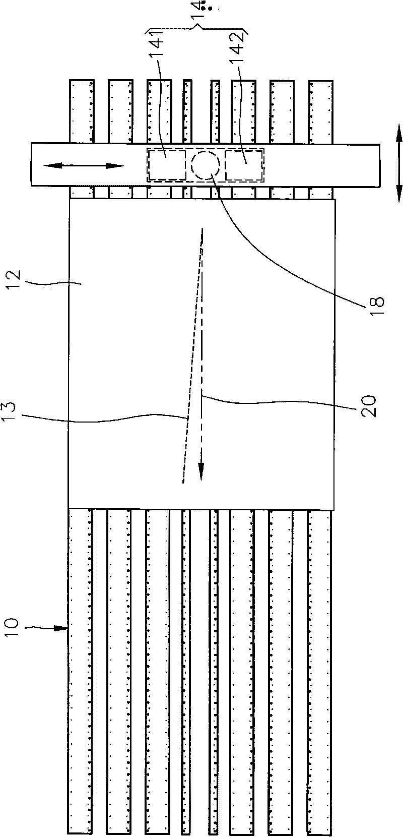
[0016] see Figure 1 to Figure 4 , a laser cutting method provided by the first preferred embodiment of the present invention, which includes the following steps: a) First, please refer to figure 2 , using a platform 10 to carry a substrate 12 , and the substrate 12 is provided with at least one first cutting line 13 . Wherein the platform 10 can be an air floating platform, and the substrate 12 can be a solar substrate; b) please refer to image 3 , use a slope calculation device 14 to capture two reference points on the first cutting line 13, and then use the two reference points to calculate the slope of the first cutting line 13 relative to the laser travel axis 20 of a laser device 18. Wherein, the slope computing device 14 includes an image capturing device 141 and a ...


PUM


Abstract

The invention relates to a laser cutting method. The method comprises the following steps: (a) bearing a substrate by using a platform, wherein the substrate is provided with at least one first cutting straight line; (b) capturing two reference points on the first cutting straight line by utilizing a slope arithmetic device, and calculating the slope of the first cutting straight line relative to the laser traveling shaft of a laser device by using the two reference points; (c) and cutting at least one second cutting straight line on the substrate by using the laser device according to the slope of the first cutting line relative to the laser traveling shaft, wherein the second cutting straight line and the first cutting straight line are at a preset interval. With the method, the process of previously making marks on the substrate can be avoided, thereby enhancing the productive capacity and reducing the cost and the expenditures.

Description

technical field [0001] The present invention relates to a positioning method for laser cutting, in particular to a laser cutting method for solar panels. Background technique [0002] During the manufacturing process of existing solar panels, lasers are required to cut thin layers in the solar panels to produce interconnected sub-cells. In this production process, the lower electrode coating is usually placed on a glass substrate first, and then the laser is used to draw parallel cutting lines at predetermined intervals to separate the lower electrode coating into several isolated areas, and then a The semiconductor coating is covered on it, and the cutting line is drawn in this layer by laser, and the cutting lines on these semiconductor coatings must be parallel and as close as possible to the cutting line on the lower electrode coating mold, and then the upper electrode coating is laid , and again use the laser to draw a cutting line on the upper electrode coating, the c...

Claims


Application Information

Patent Timeline
Patent Type & Authority Applications(China)
IPC IPC(8): H01L31/18B23K26/38B23K26/36
CPCY02P70/50
Inventor 叶公旭苏纪为
Owner CONTREL TECH CO LTD
Why Eureka
Try Eureka