
Liquid ejection head, ink cartridge, and image forming apparatus

A technology of liquid nozzles and ink cartridges, applied in printing, electrical components, printed circuits, etc., can solve the problems of disturbing image device main body size reduction and high-speed printing, and achieve the effect of reducing size and realizing box size

Active Publication Date: 2010-06-30
RICOH KK
View PDF4 Cites 7 Cited by
  • Summary
  • Abstract
  • Description
  • Claims
  • Application Information

AI Technical Summary

Problems solved by technology

In the tandem image forming apparatus, if the width of the recording head is large, the width of the scanning carriage becomes large, thereby disturbing the size reduction and high-speed printing of the main body of the image device

Method used


Image

  • Liquid ejection head, ink cartridge, and image forming apparatus
  • Liquid ejection head, ink cartridge, and image forming apparatus
  • Liquid ejection head, ink cartridge, and image forming apparatus

Examples


Embodiment Construction

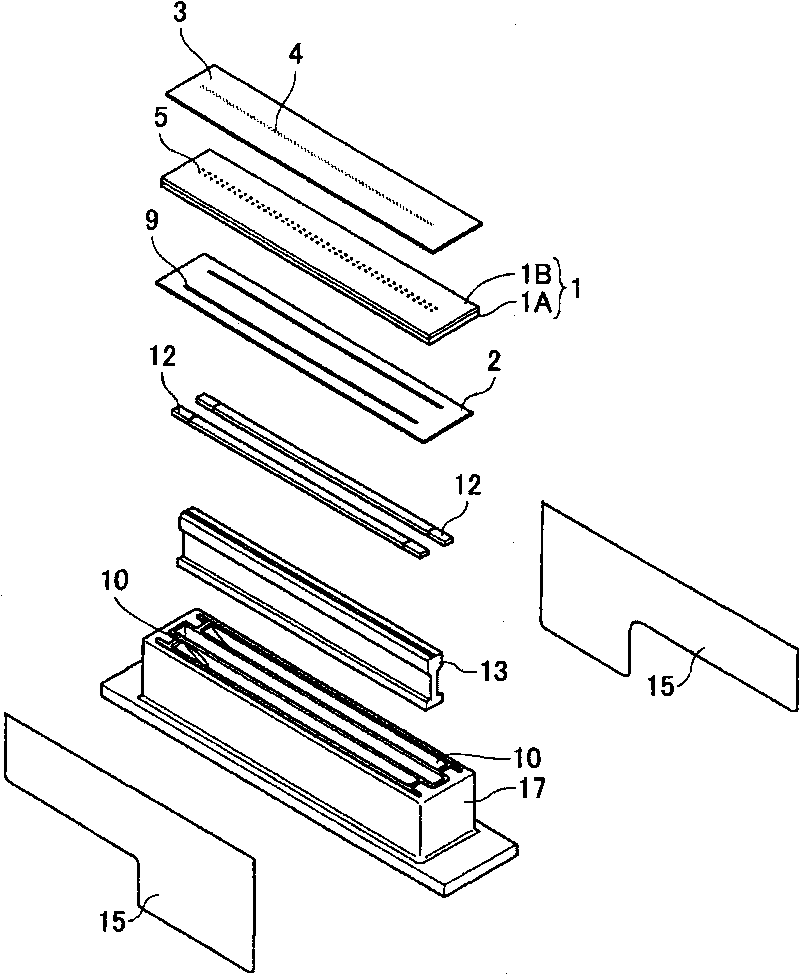
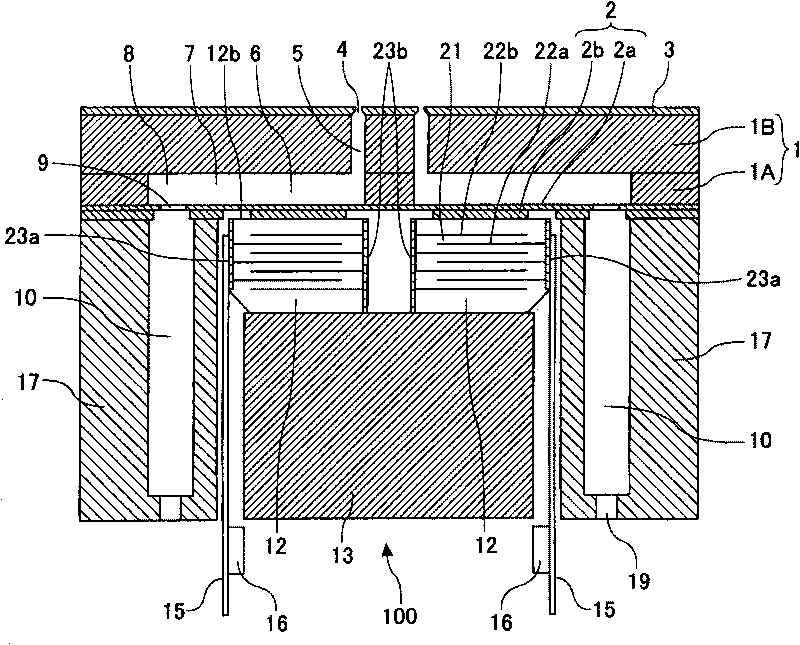
[0051] Embodiments of the present invention will be described with reference to the drawings. First, based on Figures 2 to 5 An example of a liquid jet head according to an embodiment of the present invention is explained. It should be noted that, figure 2 It is an exploded three-dimensional illustration of the head, image 3 It is an explanatory cross-sectional view along a direction (longitudinal direction of the liquid chamber) perpendicular to the nozzle installation direction of the head, Figure 4 and 5 An explanatory cross-sectional view of another example along the nozzle arrangement direction of the head (the width direction of the liquid chamber).

[0052] The liquid ejection head has a flow path substrate (liquid chamber substrate) 1 made of a SUS substrate; a vibrating plate member 2 bonded to the lower surface of the flow path substrate 1; and a nozzle plate 3 which is bonded to the upper surface of the channel substrate 1. With these components, a plurali...


PUM


Abstract

A liquid ejection head is disclosed that includes piezoelectric elements constituting driving element rows in which plural driving piezoelectric element columns that generate energy for ejecting liquid droplets from nozzles are arranged side by side; a wiring board arranged on the side opposite to a surface in which the nozzles are formed; and two sheets of flexible printed circuits that are provided to correspond to the piezoelectric elements and have output terminal parts connected to the plural driving piezoelectric element columns and input terminal parts connected to the wiring board, the input terminal parts being drawn to the side of the wiring board. The flexible printed circuits are arranged facing each other with their input terminal parts not facing each other, and the input terminal parts of the flexible printed circuits are folded in a direction where the flexible printed circuits face each other and are connected to the wiring board.

Description

technical field [0001] The present invention relates to a liquid jet head, an ink cartridge and an image forming apparatus. Background technique [0002] A general image forming (recording) apparatus, such as a printer, a facsimile, a copier, a plotter, or a multitasking machine having a plurality of such functions, includes a recording head consisting of a liquid ejection head that ejects liquid ink droplets to form an image . During image formation (recording, printing, and imaging are used synonymously), an image forming apparatus causes liquid ink droplets to adhere to a medium, and transfers the medium (hereinafter also referred to as paper, but does not limit the material; also, synonymously using a medium to be recorded, recording medium, transfer member, recording paper, etc.). [0003] It should be noted that "image forming apparatus" means an apparatus that ejects a liquid onto a medium such as paper, thread, fiber, fabric, leather, metal, plastic, glass, wood, a...

Claims


Application Information

Patent Timeline
Patent Type & Authority Applications(China)
IPC IPC(8): B41J2/045B41J2/055
CPCB41J2002/14362B41J2/04541B41J2/14274H05K1/147B41J2002/14491
Inventor 山中邦裕山口清
Owner RICOH KK
Learn More