Method for setting high temperature gas spout in convection type glass plate heating furnace and application thereof

A high-temperature gas, glass plate technology, applied in glass forming, glass tempering, glass manufacturing equipment, etc., can solve the problems affecting the heating quality of glass plates and improve the quality of tempered glass products, so as to reduce glass processing costs and avoid energy waste. , Improve the effect of heating quality

Active Publication Date: 2010-07-07
LUOYANG LANDGLASS TECH CO LTD
View PDF3 Cites 13 Cited by
  • Summary
  • Abstract
  • Description
  • Claims
  • Application Information

AI Technical Summary

Problems solved by technology

[0004] However, with the continuous deepening of the research on the glass plate heating process, the applicant found that during the heating process of the glass plate, there is a certain difference in the heat absorption speed between the edge area of ​​the glass plate and the middle area of ​​the glass plate, but it still makes the glass plate There is a temperature difference between the edge area and the middle area, and this temperature difference affects the heating quality of the glass plate and the further improvement of the quality of the final tempered glass product. Therefore, there is still room for improvement in the above-mentioned convection glass plate heating furnace

Method used


Image

  • Method for setting high temperature gas spout in convection type glass plate heating furnace and application thereof
  • Method for setting high temperature gas spout in convection type glass plate heating furnace and application thereof
  • Method for setting high temperature gas spout in convection type glass plate heating furnace and application thereof

Examples


Embodiment Construction

[0029] The present invention will now be described more fully with reference to the accompanying drawings, in which exemplary embodiments of the invention are shown. This invention may, however, be embodied in many different forms and should not be construed as limited to the exemplary embodiments set forth herein. Rather, these embodiments are provided so that this disclosure will be thorough and complete, and will fully convey the scope of the invention to those skilled in the art.

[0030] For ease of description, spatially relative terms such as "upper," "lower," "left," and "right" may be used herein to describe the relationship of one element or feature relative to another element or feature shown in the figures. It will be understood that the spatial terms are intended to encompass different orientations of the device in use or operation in addition to the orientation depicted in the figures. For example, if the device in the figures is turned over, elements described ...


PUM


Abstract

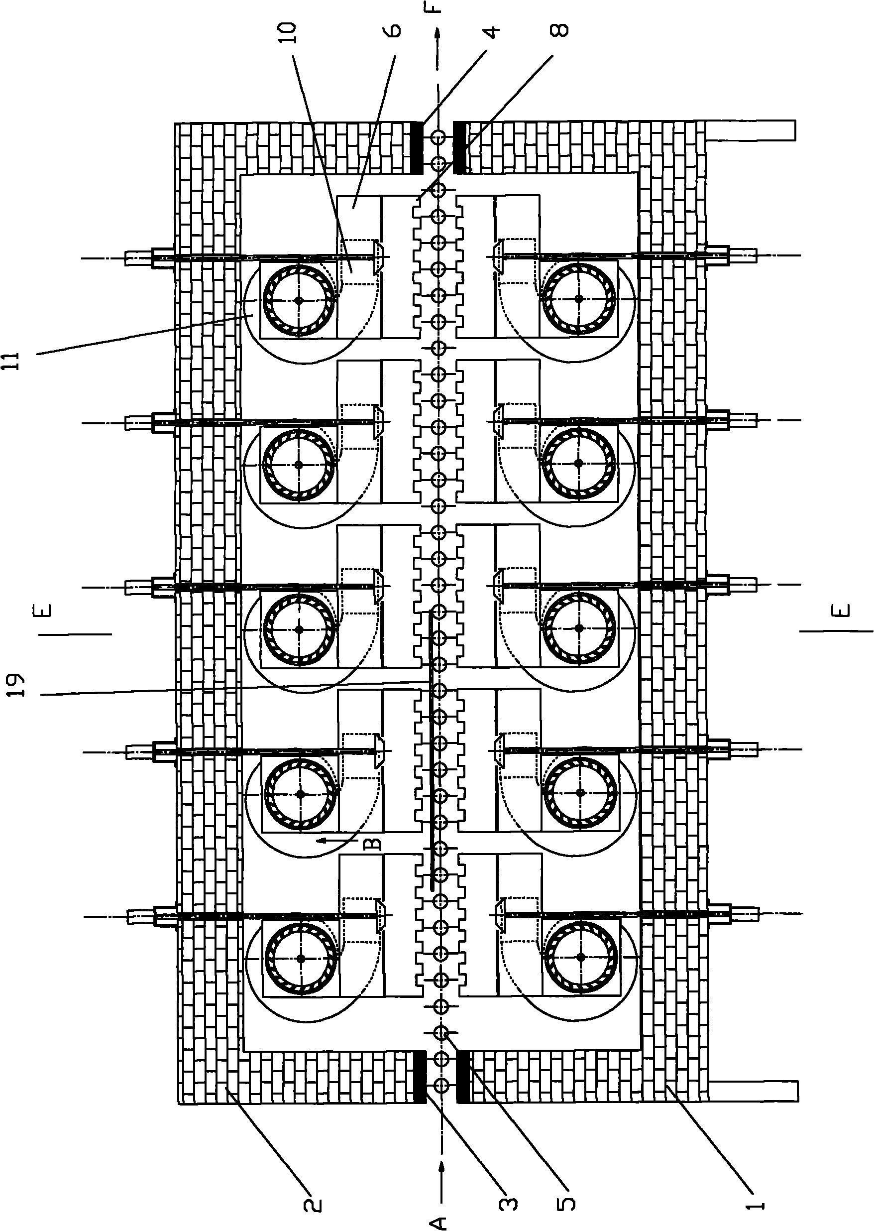
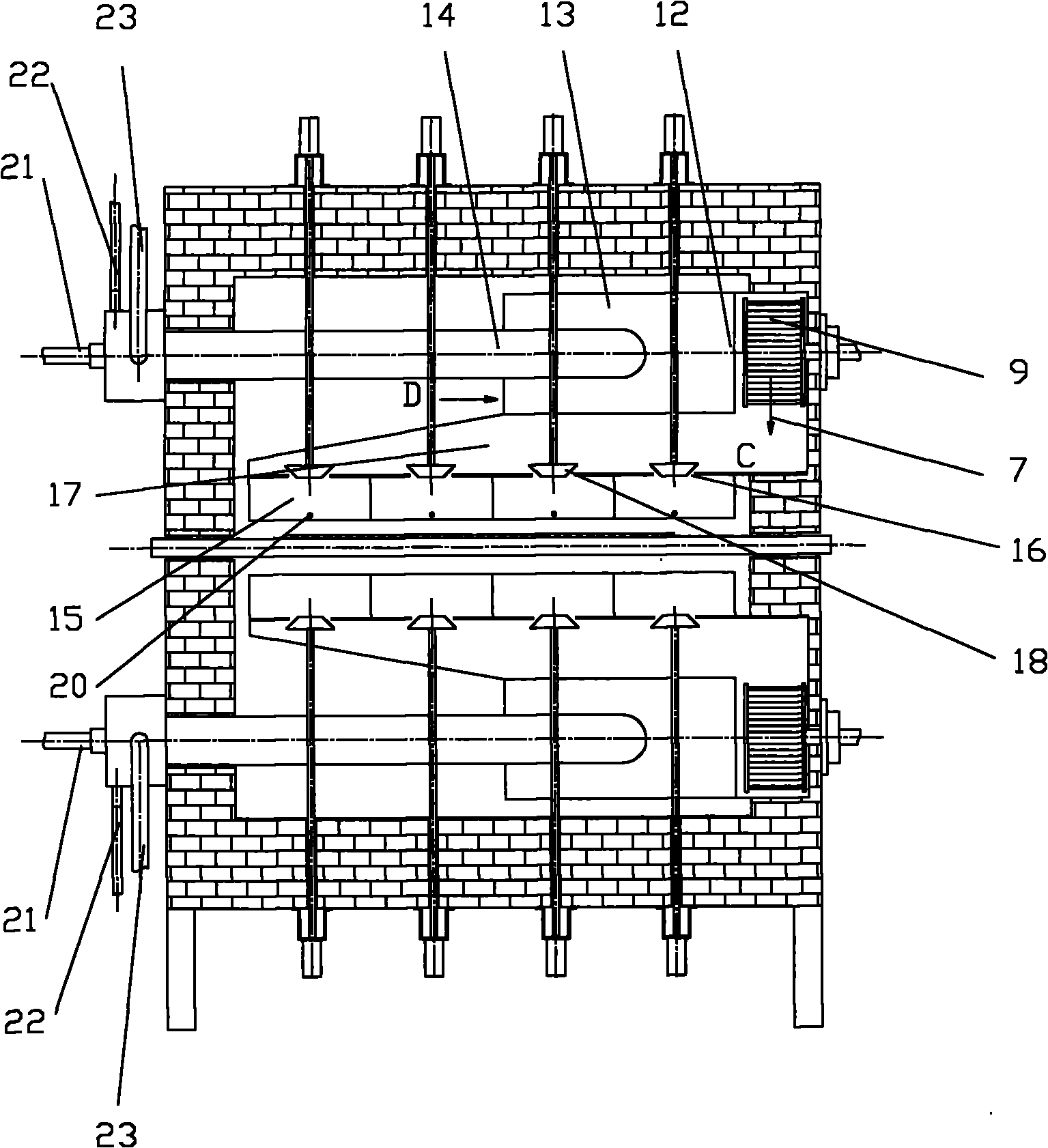
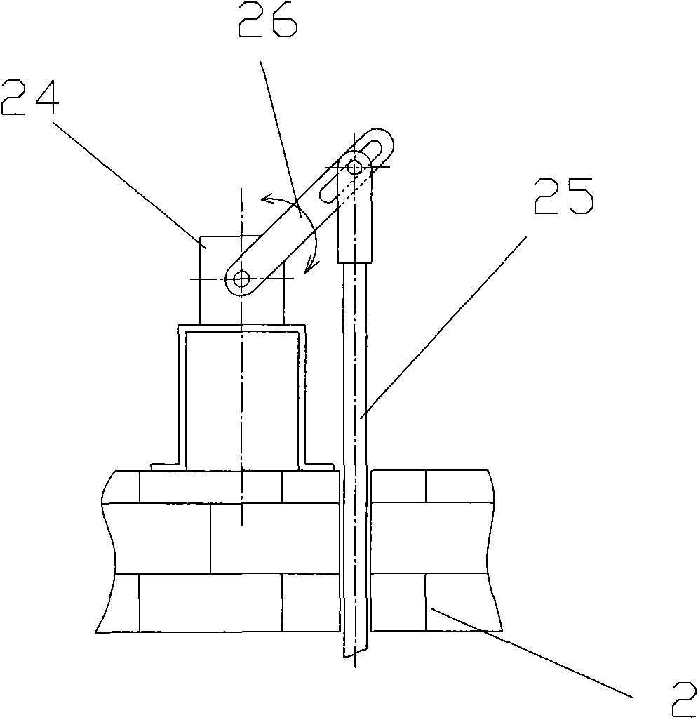
The invention discloses a method for setting a high temperature gas nozzle in a convection type glass plate heating furnace, and also discloses the convection type glass plate heating furnace designed according to the method. In the invention, all gas nozzles on a whole heating work surface in a furnace chamber are divided into units arranged in matrix, and the temperature of the gas ejected by the nozzle of each unit and/or the gas ejection amount are enabled to be adjustable and the regional control of the high temperature gas convection heating in the furnace chamber is realized; only a cell corresponding to the size of a glass plate can be started to work when a small glass plate is processed, thereby avoiding the waste of energy; and the heating uniformity of the whole glass plate can be ensured by respectively adjusting the heat of different parts of the glass plate applied by each unit when a glass plate with a bigger size is processed, thus the property of the heating furnace is greatly improved, and the technical support is provided for improving the heating quality of the glass plate and reducing the glass processing cost.

Description

technical field [0001] The invention relates to a method for setting a high-temperature gas nozzle in a convection type glass plate heating furnace, and a convection type glass plate heating furnace using the setting method. Background technique [0002] The applicant had previously applied for a Chinese invention patent with the patent number 200410046386.6 and the name "Convection Glass Plate Heating Furnace". Heating problems, and by arranging multiple gas collecting boxes in the furnace cavity along the longitudinal direction of the furnace body, the zoned control of the heating area in the furnace cavity is further realized, so that when the heating furnace processes small-sized glass plates, only It only needs to make the high-temperature spouts in local areas work, which reduces energy consumption. In addition, the use of multiple small-sized gas collection boxes also facilitates the processing, installation, adjustment and maintenance of the gas collection boxes. ...

Claims


Application Information

Patent Timeline
Patent Type & Authority Applications(China)
IPC IPC(8): C03B29/00C03B27/012C03B23/02
Inventor 李彦兵王永辉
Owner LUOYANG LANDGLASS TECH CO LTD
Why Eureka
Try Eureka