
Composite beam die and method for making composite beam with composite beam die

A technology of composite beams and molds, which is applied to the connection parts of formwork/formwork/work frame, formwork/formwork/work frame, formwork processing, etc., which can solve the problem of labor-consuming, time-consuming and material-consuming, affecting construction operation space, etc. problems, to achieve the effect of convenient construction, saving materials required for the project, and reducing impact

Inactive Publication Date: 2010-07-07
TAIZHOU BUILDING INSTALLATION ENG
View PDF4 Cites 11 Cited by
  • Summary
  • Abstract
  • Description
  • Claims
  • Application Information

AI Technical Summary

Problems solved by technology

However, there are still some defects. The concrete floor in the pouring steel-concrete composite beam still adopts the traditional construction method. It is necessary to build a full steel pipe scaffolding from the ground to support the bottom form of the floor slab and pass it on during the pouring process of the floor slab. resulting load
Setting up a full hall of steel pipe scaffolding is not only labor-intensive, time-consuming and material-intensive, but also affects the construction operation space

Method used


Image

  • Composite beam die and method for making composite beam with composite beam die
  • Composite beam die and method for making composite beam with composite beam die
  • Composite beam die and method for making composite beam with composite beam die

Examples


Embodiment Construction

[0035] The following are specific embodiments of the present invention and in conjunction with the accompanying drawings, the technical solutions of the present invention are further described, but the present invention is not limited to these embodiments.

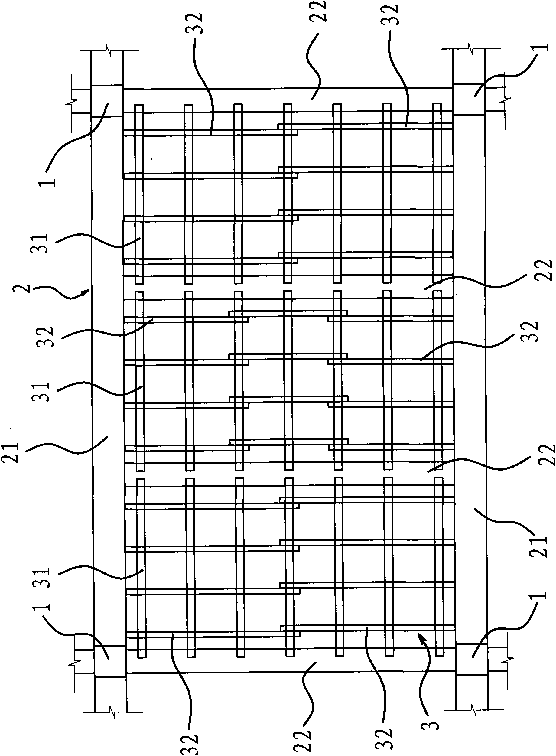
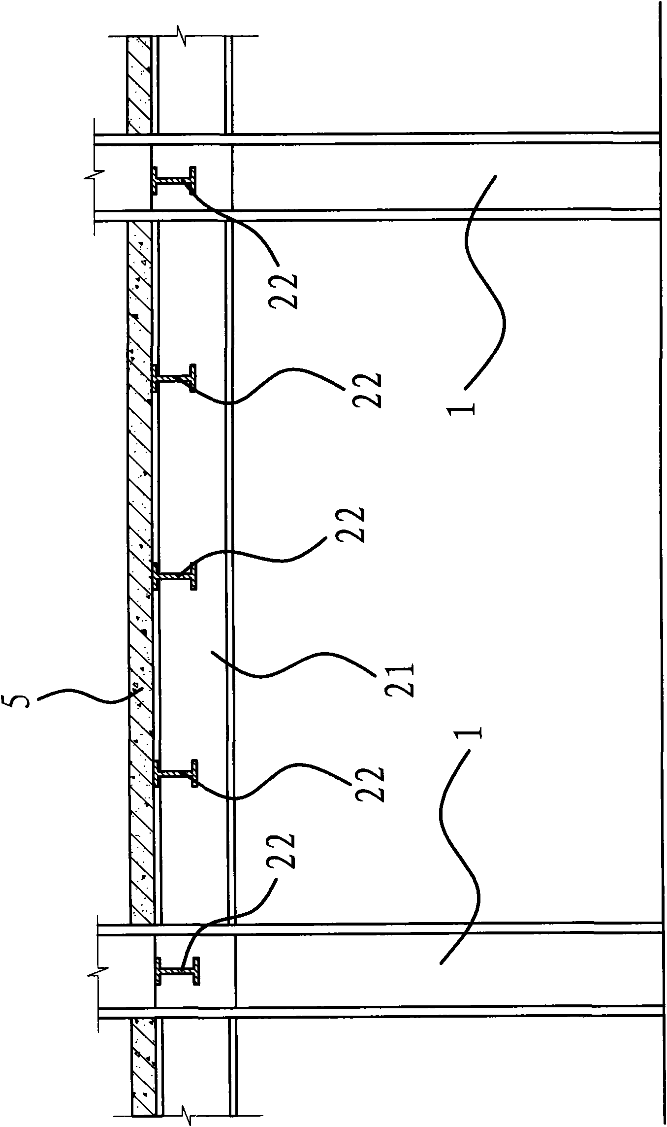
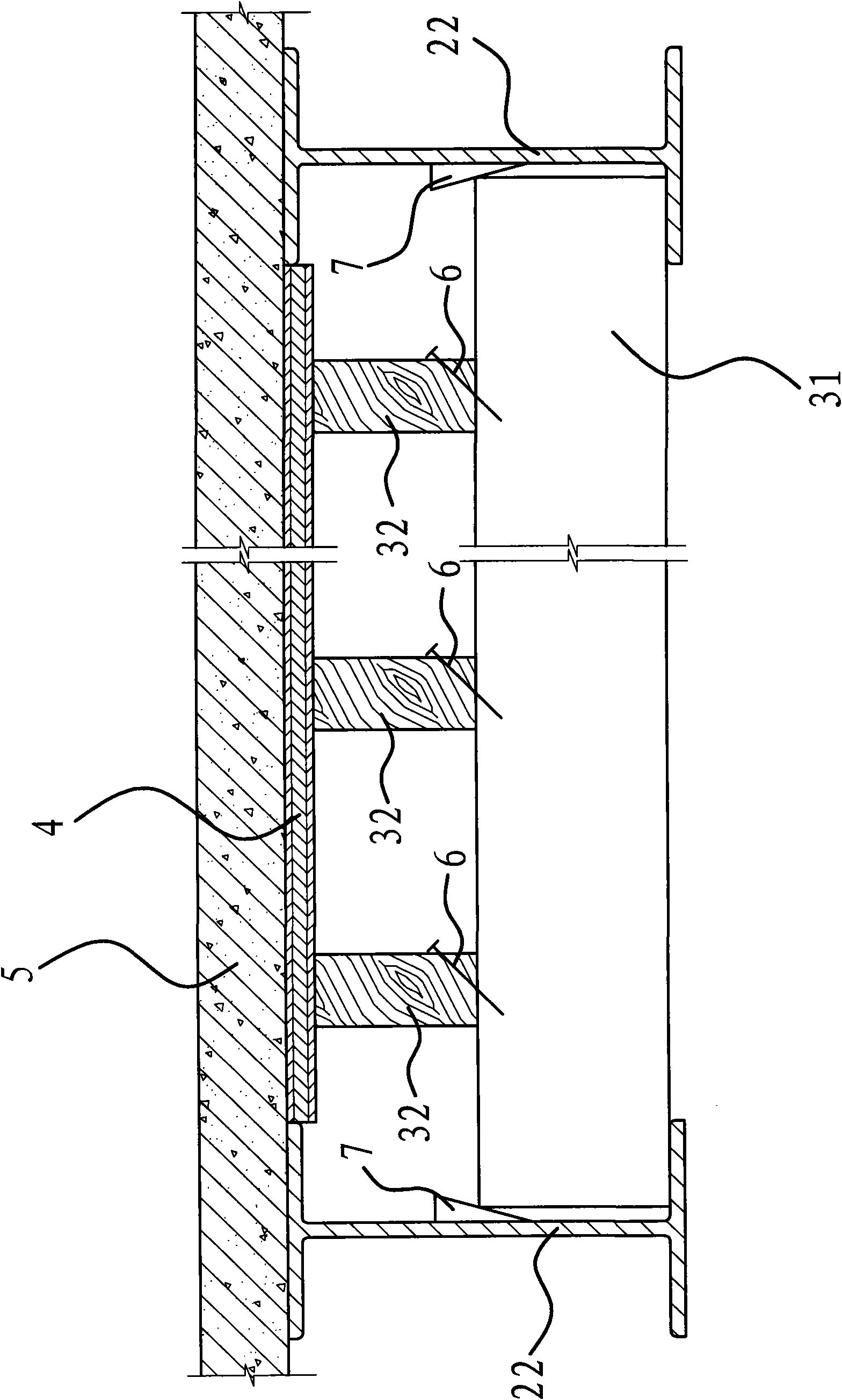
[0036] Such as image 3 As shown, the composite beam includes an I-shaped steel beam 2 fixed on the column 1 and a concrete floor 5 poured on the upper surface of the steel beam 2 . The composite beam mold includes corrugated 3 and formwork 4.

[0037] Specifically, the formwork 4 is made of plywood, and the flute 3 is made of wooden materials. In this embodiment, the flute 3 is square wood with a rectangular cross section. The flutes 3 are located on the bottom surface of the template 4 and include several main flutes 31 and several secondary flutes 32 . The main flute 31 is evenly distributed on the lower part of the formwork 4 and the two ends of the main flute 31 can be fixed on the steel beam 2. The smaller surfaces...


PUM


Abstract

The present invention provides a composite beam die and a method for making a composite beam with a composite beam die, belonging to the technical field of buildings. The present invention solves the problems that the existing concrete floor pouring method wastes labour, time and materials and influences construction operation space. The composite beam die comprises a template and a plurality of ribs uniformly arranged on the bottom surface of the template. The method for making a composite beam with a composite beam die is conducted by the following steps: mounting a girder, mounting a composite beam die, arranging steel ribs of the same length with that of an interface required on a template, pouring concrete to the interface required, forming an integral floor slab and removing the composite beam die after the concrete is hardened and molded. The composite beam die has the advantages of light dead weight, convenient production and manufacture, low price, capability of being repeatedly used and engineering cost reduction. The method for making a composite beam with a composite beam die is reasonable in design, saves materials required by engineering, reduces occupation space required by construction, and reduces influence on the normal conduction of other construction procedures.

Description

technical field [0001] The invention belongs to the technical field of buildings, and relates to a multi-storey steel structure building, in particular to a composite beam mold and a method for manufacturing composite beams by using the composite beam mold. Background technique [0002] With the rapid development of the economy, a large number of buildings and factories must be built to meet the demand. Most of the existing buildings and workshops are made of reinforced concrete. This traditional structure and construction method has problems such as heavy weight, small bearing capacity, low rigidity, many construction procedures, and slow construction speed. In order to solve the above problems, someone proposed a steel-concrete composite beam, which refers to a flexural member that combines the steel beam and the concrete floor slab through shear connectors to work together. It is currently being actively promoted. However, there are still some defects. The concrete floor...

Claims


Application Information

Patent Timeline
IPC IPC(8): E04G13/04E04G17/18E04G19/00E04B5/29
Inventor 陈宇新朱元华王志敏
Owner TAIZHOU BUILDING INSTALLATION ENG
Learn More