
Wind generator tower and lifting method thereof

A technology for wind turbines and towers, which is applied to the field of combined towers and their lifting, can solve the problems of inability to lift wind turbines, high costs, increased costs, etc., and achieves reduced installation costs, low labor intensity, and easy portability. Effect

Inactive Publication Date: 2010-07-07
尤林
View PDF0 Cites 6 Cited by
  • Summary
  • Abstract
  • Description
  • Claims
  • Application Information

AI Technical Summary

Problems solved by technology

[0002] The installation of wind turbine towers is an important part of the installation of wind turbines. The conventional method is to use cranes, which is expensive, time-consuming and labor-intensive
The hydraulic lifting tower can realize the automatic lifting of the tower, and the ordinary hydraulic lifting tower is limited by the stroke of the oil cylinder due to the use of a fixed position oil cylinder, which cannot lift the tower over 16 meters and the wind power over 1000 kg. machine
If a large-stroke, large-scale oil cylinder or lifting device is used to lift the tower of a large-scale wind turbine at one time, on the one hand, the transportation is not easy, and the conditions of the installation point cannot meet the requirements of using these large-scale equipment. installation cost

Method used


Image

  • Wind generator tower and lifting method thereof
  • Wind generator tower and lifting method thereof
  • Wind generator tower and lifting method thereof

Examples


Embodiment Construction

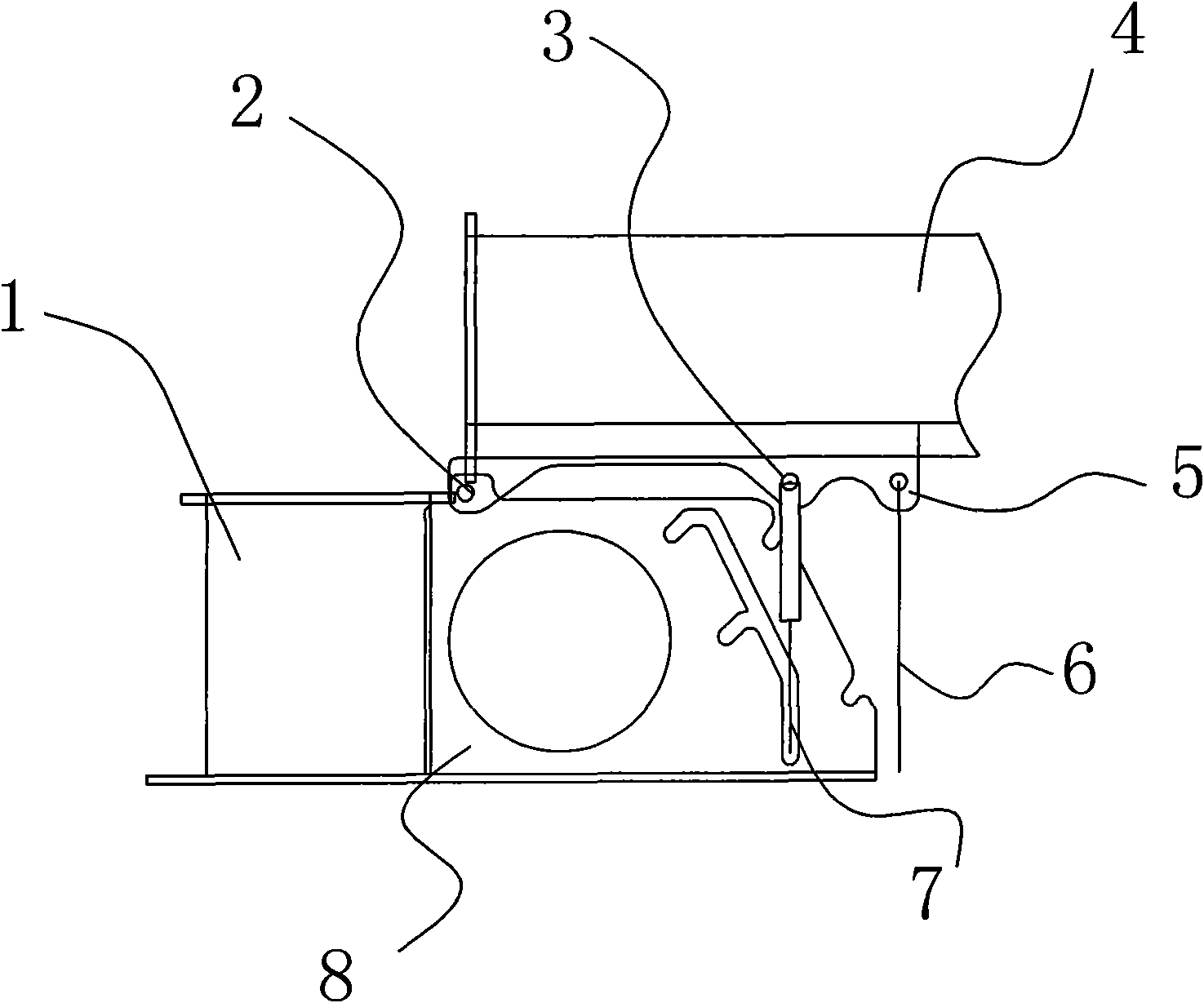
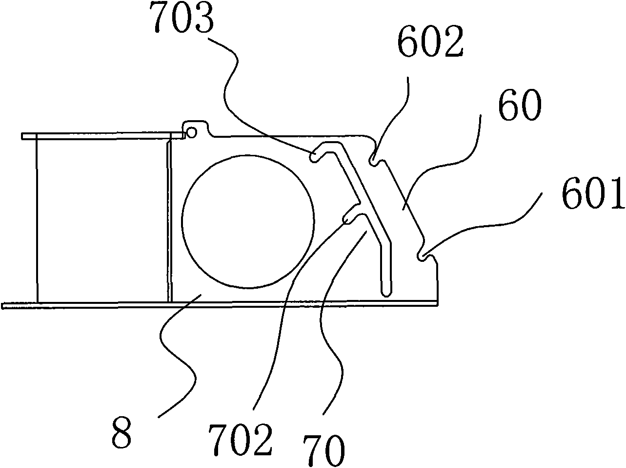
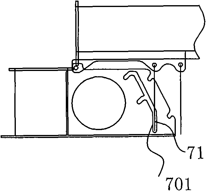
[0020] The wind power generator tower of the present invention is as figure 1 As shown, it includes a base 1 fixed on the ground, a tower 4 hinged with the base 1, the tower 4 is hinged with the base 1 through the hinge shaft 2, and the tower 4 can be leveled to an upright state relative to the base 1 through the lifting device 7 The movement of the base 1 towards the side of the tower 4 is provided with a receiving frame 8, and the tower 4 is hinged with a strut 6 through the strut hinge pin 5 near the hinge point, and the tower 4 below the strut 6 is also equipped with The connecting ear 3 of the lifting device 7 is hingedly connected; the lower end of the supporting frame 8 corresponding to the pole 6 is provided with a supporting groove group 60 , and the corresponding action end of the lifting device 7 is provided with a receiving groove group 70 .

[0021] Such as figure 2 As shown, the receiving groove group 70 on the receiving frame 8 on one side of the base 1 includ...


PUM


Abstract

The invention discloses a wind generator tower and a lifting method thereof. The invention relates to a combined tower of a wind generator and the lifting method thereof, in particular to a hinged support type tower and the lifting method thereof. The invention provides the wind generator tower which adopts an ordinary lifting device with a certain lifting force and utilizes the multi-stage operation way for realizing the large-stroke staged operation and the lifting method thereof. The wind generator tower comprises a base fixed on the ground and the tower hinged with the base, wherein the tower can carry out the motion from the horizontal state to the vertical state relative to the base through the lifting device. The wind generator tower changes the mode of fixedly arranging a lifting oil cylinder in the past, adopts the lifting device and a support which can move the positions, and realizes the lifting of the large tower through the staged elongation of the lifting device. The lifting device can adopt a smaller hydraulic cylinder, an electro-hydraulic push rod, a mechanical jack and the like, thereby facilitating the carrying, simplifying the operation and reducing the mounting cost. The safety is high and the labor intensity is small during the lifting operation.

Description

technical field [0001] The invention relates to a combined tower of a wind power generator and a lifting method thereof, in particular to a hinged tower and a lifting method thereof. Background technique [0002] The installation of wind turbine towers is an important part of installing wind turbines. The conventional method is to use cranes, which is expensive, time-consuming and labor-intensive. The hydraulic lifting tower can realize the automatic lifting of the tower, and the ordinary hydraulic lifting tower is limited by the stroke of the oil cylinder due to the use of a fixed position oil cylinder, which cannot lift the tower over 16 meters and the wind power over 1000 kg. machine. If a large-stroke, large-scale oil cylinder or lifting device is used to lift the tower of a large-scale wind turbine at one time, on the one hand, the transportation is not easy, and the conditions of the installation point cannot meet the requirements of using these large-scale equipment....

Claims


Application Information

Patent Timeline
Patent Type & Authority Applications(China)
IPC IPC(8): F03D11/00F03D13/10F03D13/20
CPCY02E10/722Y02E10/72
Inventor 尤林
Owner 尤林
Learn More