Plunger piston pair

A plunger pair and plunger technology, applied in the field of ultra-high pressure hydraulic components, can solve the problems of low volume efficiency of plunger pair, increase in axial size, heavy weight of plunger pair, etc., achieve compact structure and reduce oil valve body , The effect of eliminating the installation gap

Inactive Publication Date: 2011-11-09
NINGBO SAIVS MACHINERY
View PDF0 Cites 1 Cited by
  • Summary
  • Abstract
  • Description
  • Claims
  • Application Information

AI Technical Summary

Problems solved by technology

[0003] 1. Due to the split structure, the assembly is complicated
[0004] 2. Due to the split structure, the oil inlet valve and the oil outlet valve are installed on the oil valve body, and the oil valve body is installed along the axis of the plunger sleeve, which increases the axial dimension, so that the volume of the plunger pair Large, but also makes the plunger pair heavy and high cost
[0005] 3. Due to the split structure, the oil inlet valve and the oil outlet valve are installed on the plunger sleeve through the oil valve body. When the oil valve body and the plunger sleeve are installed, there is a certain gap, and the gap is easy to cause leakage, so that the plunger Vice volumetric efficiency is low

Method used


Image

  • Plunger piston pair
  • Plunger piston pair

Examples


Embodiment Construction

[0018] The present invention will be further described below in conjunction with the accompanying drawings and specific embodiments.

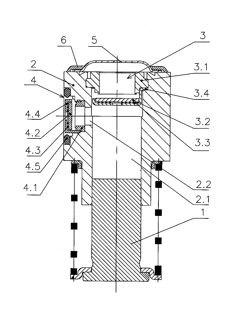
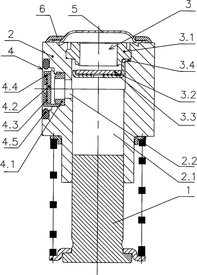
[0019] As shown in the figure, the plunger pair of the present invention includes a plunger 1, a plunger sleeve 2 with an oil chamber 2.1, an oil inlet valve 3 and an oil outlet valve 4; the oil inlet valve 3 is located on the plunger sleeve 2 At the opening of the oil chamber 2.1, the plunger sleeve 2 is provided with a radial through hole 2.2 communicating with the oil chamber 2.1, and the oil outlet valve 4 is arranged in the through hole 2.2.

[0020] The oil outlet valve 4 sequentially includes a first valve seat 4.1, a first valve plate 4.2, a first return spring 4.3, and a first fixed cover 4.4 from inside to outside; the first valve seat 4.1 is tightly fitted in the through hole 2.2 , the through hole 2.2 is a multi-stage stepped hole, the first valve seat 4.1 and the first fixed cover 4.4 are tightly fitted on the steps of the correspo...


PUM


Abstract

The present invention discloses a plunger piston pair comprising a plunger piston (1), a plunger piston sleeve (2) provided with an oil chamber (2.1), an oil inlet valve (3) and an oil outlet valve (4), wherein the oil inlet valve (3) is arranged at an opening of the oil chamber (2.1) of the plunger piston sleeve (2); the plunger piston sleeve (2) is provided with a redial through hole (2.2) communicated with the oil chamber (2.1); and the oil outlet valve (4) is arranged in the redial through hole (2.2). The plunger piston pair has the advantages of simple assembly, small volume, light weight, low cost and high volume efficiency.

Description

technical field [0001] The invention relates to an ultra-high pressure hydraulic component, in particular to a structurally integrated plunger pair. Background technique [0002] The plunger pair is a component of the plunger pump. The current plunger pair is divided in structure. When the plunger pump is assembled, the plunger, plunger sleeve, oil inlet valve, oil outlet valve, spring And two spring seats are assembled together to form a plunger pair; the plunger sleeve is provided with oil chambers distributed along its axis, one of the two spring seats fits on the outer circumference of the plunger, and the other Installed on the outer circumference of the plunger sleeve, the two ends of the spring respectively abut against two spring seats, and the plunger slides with the plunger sleeve under the action of oil pressure, and is reset by the spring. Both the oil inlet valve and the oil outlet valve are installed in an oil valve body, and are installed at the opening of th...

Claims


Application Information

Patent Timeline
Patent Type & Authority Patents(China)
IPC IPC(8): F04B53/14
Inventor 周重威
Owner NINGBO SAIVS MACHINERY
Why Eureka
Try Eureka