Retainer of spherical thrust roller bearing for rolling mill
A technology of thrust self-aligning rollers and cages, applied in the field of thrust bearings, can solve problems such as difficult assembly, achieve compact structure, convenient assembly and disassembly, and improve working conditions
Inactive Publication Date: 2010-07-07
瓦房店鹏东轴承制造有限公司
View PDF0 Cites 4 Cited by
- Summary
- Abstract
- Description
- Claims
- Application Information
AI Technical Summary
Problems solved by technology
[0004] In order to solve the above technical problems, the present invention provides a cage for thrust self-aligning roller bearings for rolling mills, which solves problems such as difficult assembly
Method used
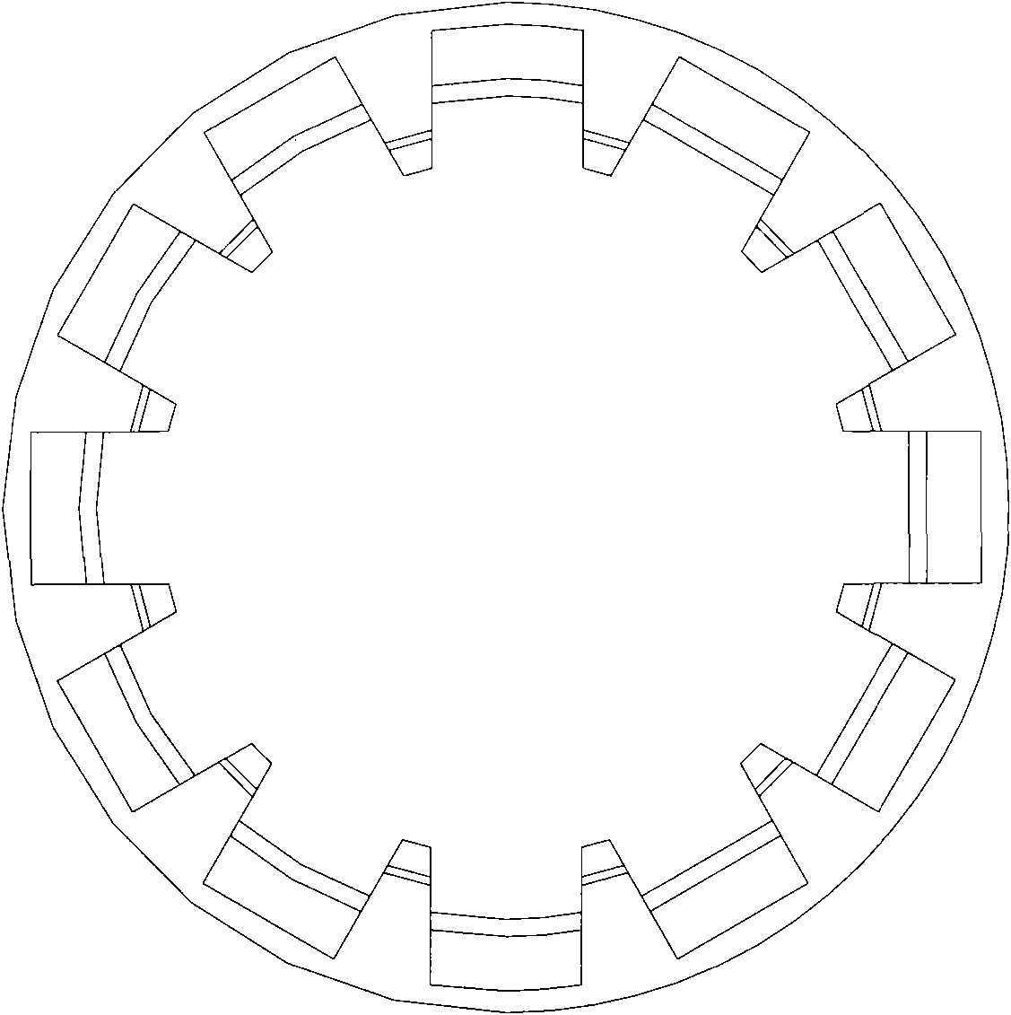
View moreImage
Smart ImageViewing Examples
Examples
Embodiment approach
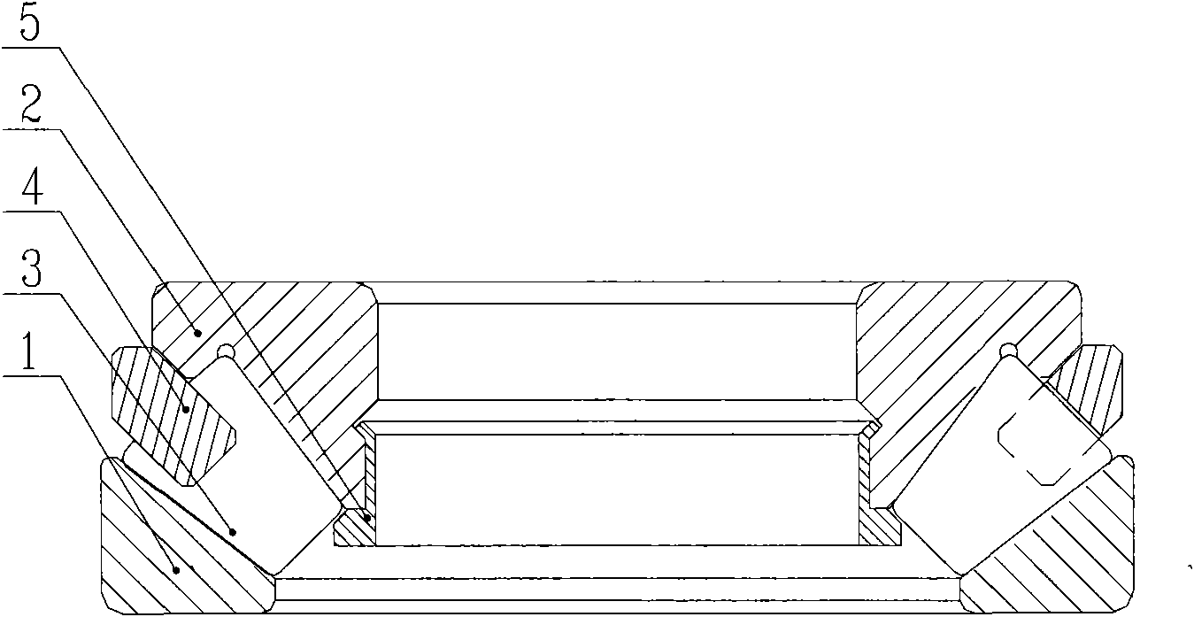
[0011] A preferred embodiment: Taking a thrust spherical roller bearing with a nominal outer diameter of 360mm as an example, the nominal outer diameter of the cage ring is 351mm, the nominal outer diameter of the cage ring is 327mm, and the cone inclination angle is 44° .
Login to View More PUM
 Abstract
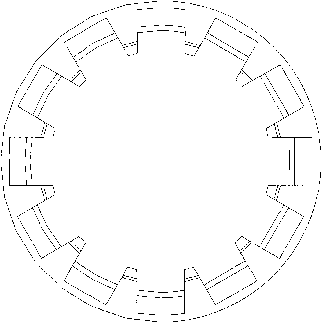
The invention discloses a retainer of a spherical thrust roller bearing for a rolling mill; a tapered ring is arranged at one side of the retainer, inclined teeth are uniformly distributed at the other side of the retainer, and teeth are embedded on the tapered ring, spaces for containing cylindrical rollers are formed among the teeth, the teeth are uniformly distributed and arrayed on a circular ring; the outer diameter surface and the inner diameter surface of the tooth are consistent to the outer diameter surface and the inner diameter surface of the tapered ring, and two inner end surfaces of the teeth are planes; two sides of the outer end surface of each tooth are rounded off; the retainer of the spherical thrust roller bearing for the rolling mill has the advantages of compact structure, perfect sealing, convenient assembly and disassembly, and large automatic aligning amplitude, so as to improve the working condition and greatly improve the bearing life.
Description
technical field [0001] The invention relates to a cage of a thrust self-aligning roller bearing for a rolling mill, belonging to the technical field of thrust bearings. Background technique [0002] Thrust self-aligning roller bearings have the advantages of compact structure, perfect sealing, convenient assembly and disassembly, and large self-aligning range. The axial load shall not exceed 55% of the axial load. Compared with other thrust bearings, this kind of bearing has a lower friction coefficient, higher speed and self-aligning performance. The thrust self-aligning bearings listed in this invention are reinforced bearings with optimized design. The rollers of this kind of bearing are asymmetric spherical rollers, which can reduce the relative sliding between the rollers and the raceway during work, and the rollers are long, large in diameter, large in number and high in load capacity, and are usually lubricated with oil. Grease can be used for individual low-speed ...
Claims
Login to View More Application Information
Patent Timeline
 IPC IPC(8): F16C33/46
Inventor 李连鹏陶淑媛李连宙王震江刘勇邓爱秋陈维秀
Owner 瓦房店鹏东轴承制造有限公司
- R&D Engineer
- R&D Manager
- IP Professional
- Industry Leading Data Capabilities
- Powerful AI technology
- Patent DNA Extraction
Learn More Browse by: Latest US Patents, China's latest patents, Technical Efficacy Thesaurus, Application Domain, Technology Topic, Popular Technical Reports.
© 2024 PatSnap. All rights reserved.Legal|Privacy policy|Modern Slavery Act Transparency Statement|Sitemap|About US| Contact US: help@patsnap.com


