Combined on-off control system

A control system and combination switch technology, applied in the direction of automatic disconnection of emergency protection devices, instruments, electrical components, etc., can solve problems such as fire or explosion, leakage, etc., to enhance real-time performance, reduce device costs, and shorten protection time. Effect

Active Publication Date: 2012-10-03
BEIJING HOLLYSYS AUTOMATION & DRIVE
View PDF3 Cites 0 Cited by
  • Summary
  • Abstract
  • Description
  • Claims
  • Application Information

AI Technical Summary

Problems solved by technology

[0003] In addition, in the power grid system, there will inevitably be leakage, and in some occasions, the electric spark or arc generated by the leakage may lead to dangerous situations. Risk of fire or explosion

Method used


Image

  • Combined on-off control system
  • Combined on-off control system
  • Combined on-off control system

Examples


Embodiment 1

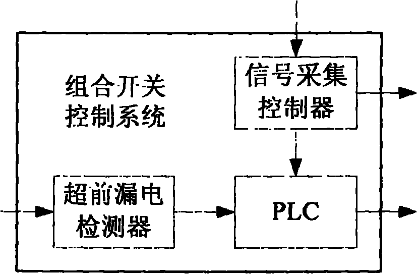
[0055] Embodiment 1, a combination switch control system, such as figure 1 shown, including:

[0056] PLC, a signal acquisition controller and an advanced leakage detector connected to the PLC respectively;

[0057] The signal acquisition controller is used to collect three-phase AC current, and compare it with the preset current threshold value to determine whether it is over-current; when it is over-current, determine whether to perform fast protection, and if so, output the first switch control signal; otherwise sending a protection signal to the PLC;

[0058] The lead leakage detector is used to measure the resistance value of the leakage resistance and send it to the PLC;

[0059] The PLC is used to judge whether the resistance of the leakage resistor is less than a preset resistance threshold, and output a second switch control signal if less; and output a second switch control signal when receiving the protection signal.

[0060] In this embodiment, the signal acquisit...


PUM


Abstract

The present invention discloses a combined on-off control system. The system comprises a programmable logic controller (PLC), a signal acquisition controller and an advance electricity leakage detector. The signal acquisition controller and the advance electricity leakage detector are respectively connected with the PLC. The signal acquisition controller is used for acquiring three phase AC current, comparing the three phase AC current with a preset current threshold value and judging whether overcurrent occurs or not. When overcurrent occurs, whether quick protection is to be carried out or not is judged. If quick protection is to be carried out, output first on-off control signals. Otherwise, send protection signals to the PLC. The advance electricity leakage detector is used for measuring the resistance of an electricity leakage resistor and sending the resistance to the PLC. The PLC is used for judging whether the resistance of an electricity leakage resistor is smaller than a preset resistance threshold value or not. If the resistance is smaller than the preset resistance threshold value, output second on-off control signals. The second on-off control signals are output according to the protection signals. The system can acquire data in environments and carry out quick overcurrent protection and advance electricity leakage protection.

Description

technical field [0001] The invention relates to circuit protection technology, in particular to a combination switch control system. Background technique [0002] The existing three-phase AC current acquisition and overcurrent protection generally collect AC signals and convert them into DC signals, and then a circuit such as PLC performs current detection on the DC signals to determine whether the DC signals exceed the preset DC threshold. In this way, it is judged whether the AC signal is in an overcurrent state; finally, appropriate protection measures are taken according to the judgment result if necessary. In the prior art, due to the conversion process of AC to DC, the time cost is relatively large, and conversion devices such as transmitters are required to complete the conversion from AC to DC, and the device cost is also high. [0003] In addition, in the power grid system, there will inevitably be leakage, and in some occasions, the electric spark or arc generated...

Claims


Application Information

Patent Timeline
Patent Type & Authority Patents(China)
IPC IPC(8): H02H3/08H02H3/14G01R31/02
Inventor 王国锋徐昌荣徐毓军石鹏侯爱林张军
Owner BEIJING HOLLYSYS AUTOMATION & DRIVE
Why Eureka
Try Eureka