Method and network side device for transmitting physical random access channel

A technology of physical random access and network-side equipment, which is applied in the communication between multiple stations, multi-frequency code systems, etc., to ensure performance, achieve performance and efficiency, and reduce overhead.

Inactive Publication Date: 2010-07-07
CHINA ACAD OF TELECOMM TECH
View PDF0 Cites 21 Cited by
  • Summary
  • Abstract
  • Description
  • Claims
  • Application Information

AI Technical Summary

Problems solved by technology

[0012] The present invention provides a method for transmitting a physical random access channel and network side equipment to solve the problem that the short RACH format has not been introduced in the prior art

Method used


Image

  • Method and network side device for transmitting physical random access channel
  • Method and network side device for transmitting physical random access channel
  • Method and network side device for transmitting physical random access channel

Examples


Embodiment 1

[0048] Figure 7 It is a schematic diagram of the time-frequency position of PRACH in a subframe. As shown in the figure, the short RACH (dark part) is configured as a fixed position of a UL (UL Up-Link, uplink) subframe in time, for example Only the first 2 symbols of a subframe are occupied (the 2 symbols are only used as an example, and may be other values), and the frequency domain can be configured on any continuous 6 PRBs. There is at most one PRACH channel in each subframe.

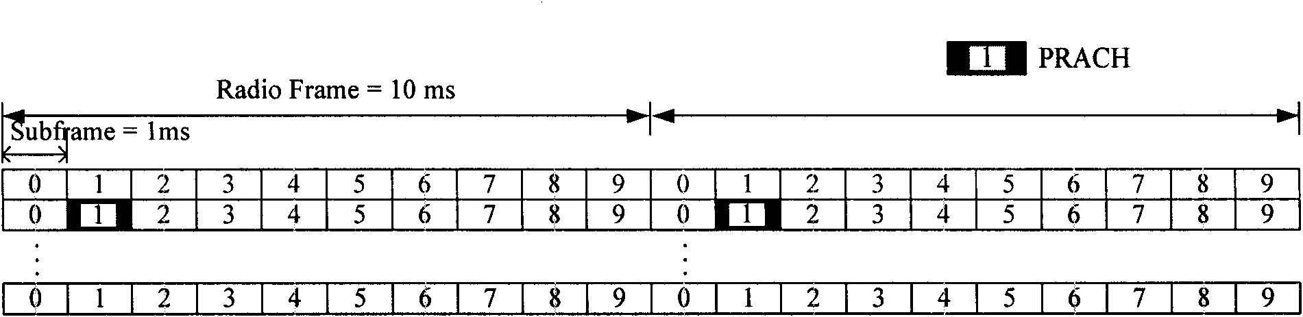
[0049] Figure 8 It is a schematic diagram of a configuration of PRACH in a radio frame, wherein, Figure 7 Emphasis is the position of PRACH in a subframe, and Figure 8 If a wireless frame is configured with multiple PRACHs, select certain subframe configurations; select a subframe and configure multiple PRACHs on this subframe as follows Figure 9 shown.

[0050] In implementation, the channel time-frequency position and density configuration of the PRACH can reuse the existing FDD configurat...

Embodiment 2

[0052] Figure 9 It is a schematic diagram of the configuration of multiple PRACHs under FDM (Frequency DivisionMultiplexing, Frequency Division Multiplexing) in one subframe, Figure 1 There are 3 short RACH channels in each subframe, which are marked with different lines in the figure. As shown in the figure, the short RACH is configured as a fixed position in a subframe in time, for example, it only occupies the first 2 channels of a subframe. Symbols and frequency domains can be configured on any 6 consecutive PRBs. Multiple PRACH channels exist in each subframe.

Embodiment 3

[0054] Figure 10 It is a schematic diagram of the configuration of multiple PRACHs under TDM (Time Division Multiplexing, time division multiplexing) in one subframe, Figure 1 There are 3 short RACH channels in each subframe, which are marked with different lines in the figure. As shown in the figure, the short RACH occupies 2 symbols in time, and can be configured on any 2 symbols in time, and can be configured in the frequency domain. on any 6 consecutive PRBs. In practice, the configuration starts with even symbols.

[0055] Compared with Embodiments 1 and 2, an additional signaling needs to be introduced in this embodiment to indicate the specific time-domain starting point of the PRACH channel, that is, the occupied OFDM symbol.

[0056] Similarly, the channel frequency domain position and density configuration of the PRACH can reuse the existing FDD configuration.

[0057] When transmitting the PRACH in step 603, multiple PRACH channels can be time-division multiple...


PUM


Abstract

The invention discloses a method and network side device for transmitting physical random access channel. The method comprises the following steps: fixing or signal setting the positions of the physics random access channel in time domain and frequency domain according to sequence length; and transmitting physics random access channel. By using the method of the invention, multiple physics random access channels can be selected according to the application scenarios, and the cost can be reduced as much as possible while performance is guaranteed, thus realizing the balance between performance and efficiency.

Description

technical field [0001] The invention relates to wireless communication technology, in particular to a method for transmitting a physical random access channel and network side equipment. Background technique [0002] RACH (RACH Random Access Channel, random access channel) is used for random access of uplink data, to ensure that UE (User Equipment, user equipment) quickly accesses the system and completes uplink synchronization at the same time. At present, the PRACH (Physical Random Access Channel, physical random access channel) channel design in the LTE (Long Term Evolution, long-term evolution) system is as follows: [0003] figure 1 It is a schematic diagram of the sequence structure of the physical random access channel. As shown in the figure, the PRACH includes: CP (Cyclic preamble, cyclic prefix), GT (Guard time, guard interval), and Preamble (preamble). Among them, there are three parts in LTE The formats of the five random access preambles are as follows: [00...

Claims


Application Information

Patent Timeline
Patent Type & Authority Applications(China)
IPC IPC(8): H04L27/26H04B7/26
Inventor 肖国军潘学明孙韶辉索士强
Owner CHINA ACAD OF TELECOMM TECH
Why Eureka
Try Eureka