Multi-resonance circuit suitable for LED multi-path precise constant current driver

A constant-current drive, multi-resonance technology, applied in electric lamp circuit layout, electric light source, lighting device, etc., can solve the problems of high power consumption of linear adjustment tube and heating of LED driver, and achieve low cost, high reliability, and current sharing. high precision effect

Inactive Publication Date: 2013-01-16
INVENTRONICS HANGZHOU
View PDF0 Cites 0 Cited by
  • Summary
  • Abstract
  • Description
  • Claims
  • Application Information

AI Technical Summary

Problems solved by technology

Although the circuit cost of this solution is low and the current sharing of each LED is good, short circuit is a common failure mode of LEDs. When the voltage difference of multiple LEDs is relatively large, the power consumption of the linear adjustment tube is very large, which makes the LED driver seriously heat.

Method used


Image

  • Multi-resonance circuit suitable for LED multi-path precise constant current driver
  • Multi-resonance circuit suitable for LED multi-path precise constant current driver
  • Multi-resonance circuit suitable for LED multi-path precise constant current driver

Examples


Embodiment Construction

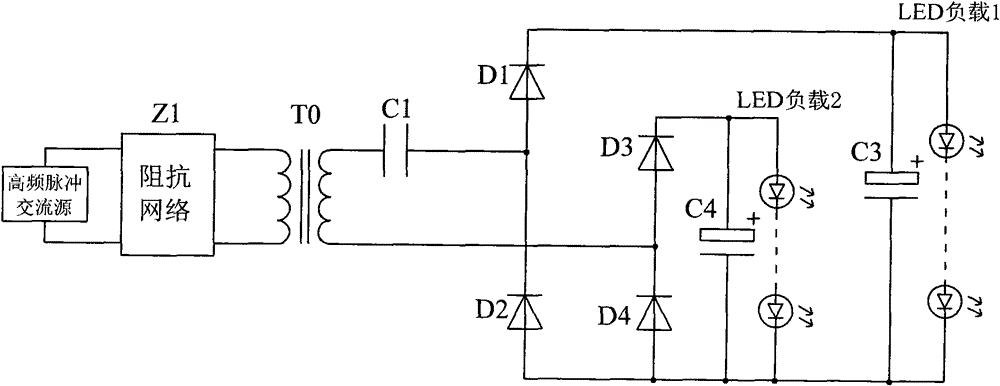
[0048] refer to image 3 , the first multi-resonant circuit block diagram for precise constant current drive of two LEDs, including high-frequency pulse AC source, impedance network Z1, resonant capacitor C1, high-frequency transformer T0, two-way rectifier filter circuit and LED load, specifically For example: the input of the impedance network Z1 is a high-frequency pulse AC source, and its output terminal is connected to the primary side of the high-frequency transformer T0, and one end of the secondary winding of the high-frequency transformer T0 is connected to one end of the resonant capacitor C1, and the resonant capacitor The other end of C1 is connected to the anode of diode D1 and the cathode of diode D2, the other end of the secondary winding of the high-frequency transformer is connected to the anode of diode D3 and the cathode of diode D4, and the anodes of diodes D2 and D4 are connected and connected to the negative of LED load 1 and 2. The positive terminal of L...


PUM


Abstract

The invention discloses a multi-resonance circuit suitable for an LED multi-path precise constant current driver. The multi-resonance circuit comprises a high-frequency pulse AC source, an impedance network, a resonance capacitor, a high-frequency transformer, two-path rectifying filter circuits and two-path LED loads, wherein the high-frequency resonance capacitor and the impedance network form a high-frequency resonance network which participates in the resonant transformation of a main circuit and has a blocking function, namely, balancing the voltage differences of the two-path LED loads to equalize the average current flowing through the two-path LED loads; and under an ideal condition, when the voltage drop of the two-path LED loads are completely equal, the voltages at the two endsof the resonance capacitor are zero. The multi-resonance circuit has the advantages of: 1, achievement of equalizing current among the multi-path LED loads through a primary converting circuit, low cost, no need of additional control circuits, and high reliability; 2, high precision of equalizing current, and insusceptibility to the voltage differences of the two-path LED loads; 3, high efficiency of the achievement of the equalizing current through a blocking capacitor, and little loss in the achievement of the equalizing current even if the voltage differences of the two-path LED loads are large.

Description

technical field [0001] The invention relates to a circuit capable of realizing accurate constant current driving of LEDs. Specifically, it should be a multi-component resonant circuit to realize constant current drive of two or more LED loads. Background technique [0002] For the application of LED multi-channel constant current control driver, the most commonly used solutions are: 1. Constant voltage module + multi-channel non-isolated DC / DC constant current circuit (such as BUCK circuit); 2. Voltage adjustable voltage regulator module + multi-line Sexually adjust the constant current circuit. [0003] For the first option, refer to figure 1 , the output of the constant voltage module is used as the input of multiple constant current circuits, and each constant current circuit is independently controlled by constant current, which can easily ensure the current sharing of multiple output currents. However, because the voltage of the constant voltage module and the voltag...

Claims


Application Information

Patent Timeline
Patent Type & Authority Patents(China)
IPC IPC(8): H05B37/02
Inventor 吴新科姚晓莉葛良安
Owner INVENTRONICS HANGZHOU
Why Eureka
Try Eureka