Transmission structure of food processor
A technology of food cooking machine and transmission structure, which is applied in the field of transmission structure of food cooking machine, which can solve the problems of bad hand feeling, loud noise and large vibration, and achieve the effects of reducing noise, improving service life, reducing vibration and friction
- Summary
- Abstract
- Description
- Claims
- Application Information
AI Technical Summary
Problems solved by technology
Method used
Image
Examples
no. 1 example
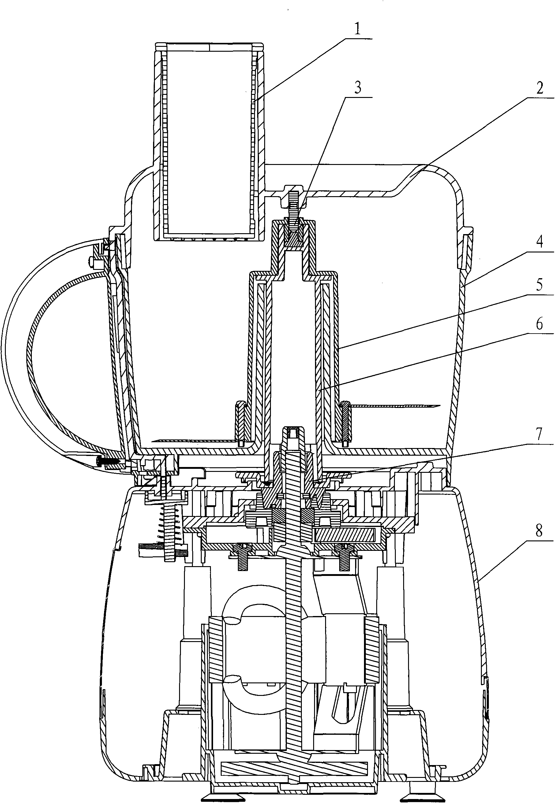
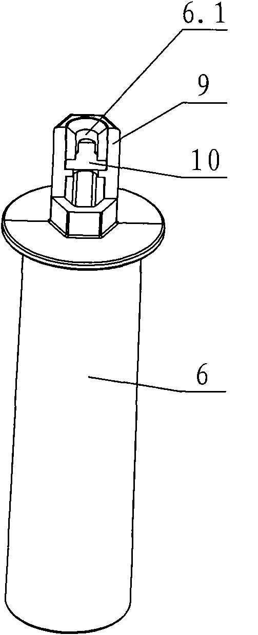
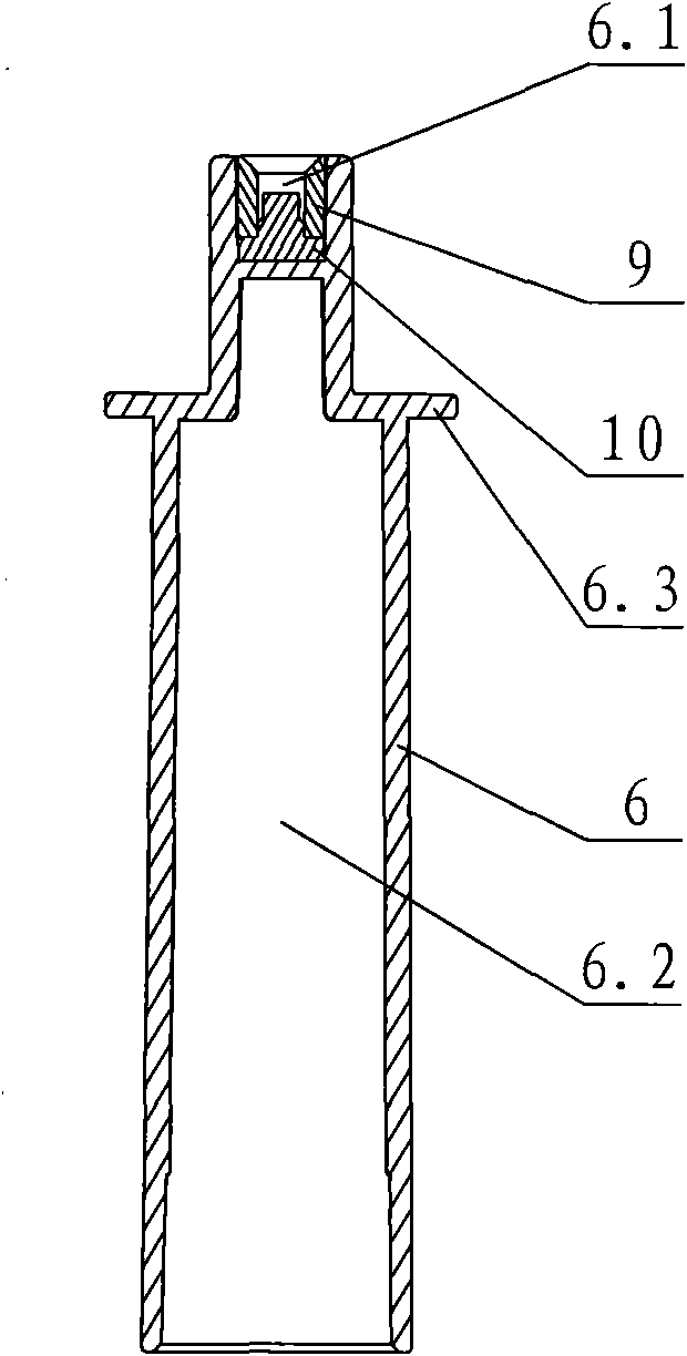
[0022] see Figure 1-3 , the transmission structure of this food cooking machine includes a stirring cup 4 and a measuring cup 1 arranged on the upper part of the main machine 8, a stirring knife assembly 5 is arranged in the stirring cup 4, an opening is arranged on the top of the stirring cup 4, and a cup cover 2 is arranged on the opening, The cup cover and the stirring cup 4 are rotated and fastened, and the positioning shaft 3 is arranged in the cup cover 2. The stirring knife assembly 5 is connected with the connector 7 of the main machine 8 through a foldable spindle assembly. The spindle assembly includes a rotating shaft 6 and a shaft sleeve 9. The rotating shaft and the axle sleeve 9 are an interference fit, which eliminates the gap between the rotating shaft 6 and the axle sleeve 9 .
[0023] The cross section of the rotating shaft 6 is a cylindrical shape with a small upper part and a larger lower part. The upper part of the rotating shaft 6 is provided with a baff...
no. 2 example
[0026] see Figure 4-5 , the elastic member is a compression spring 12 and a top bead 11, the top of the top bead is similar to a boss shape; the top of the top bead 11 is socketed with the sleeve 9, the bottom of the top bead 11 is against the top of the compression spring 12, and the shaft 6 A trapezoidal installation cavity 6.2 is provided, and a boss is provided on the top surface of the baffle 6.3, and the compression spring 12 is overlaid on the boss of the baffle 6.3. The sleeve 9 is integrated with the rotating shaft 6, so that the elastic member will not slide upwards; the top ball 11 can move up and down by the elastic force of the compression spring 12, and other parts not described are the same as the first embodiment.
PUM
 Abstract
Description
Claims
Application Information
 - R&D
- Intellectual Property
- Life Sciences
- Materials
- Tech Scout
- Unparalleled Data Quality
- Higher Quality Content
- 60% Fewer Hallucinations
Browse by: Latest US Patents, China's latest patents, Technical Efficacy Thesaurus, Application Domain, Technology Topic, Popular Technical Reports.
© 2025 PatSnap. All rights reserved.Legal|Privacy policy|Modern Slavery Act Transparency Statement|Sitemap|About US| Contact US: help@patsnap.com


