
High-speed laser cladding processing machine tool and processing method

A technology of laser cladding and machining machine tools, applied in metal processing equipment, grinding machine parts, grinding machines, etc., can solve the problems of increasing the axial constraint of the workpiece due to thermal expansion, reducing the strength of the workpiece, increasing the amount of deformation, etc. The effect of avoiding processing quality, reducing cracking and alleviating stress concentration

Inactive Publication Date: 2020-07-28
山东高锻机械有限公司
View PDF0 Cites 3 Cited by
  • Summary
  • Abstract
  • Description
  • Claims
  • Application Information

AI Technical Summary

Problems solved by technology

[0003] Although laser cladding technology is superior to some traditional technologies, laser cladding technology uses high-energy laser beams as the heat source processing process, and the strength of the workpiece will decrease under high temperature conditions.
In addition, during the heating and cooling process, the temperature changes of various parts of the workpiece are difficult to be completely consistent. The asynchronous nature of this temperature change will cause changes in the thermal stress and tissue stress of the workpiece. When the plastic resistance of a certain part of the workpiece is under high temperature, irreversible thermal deformation will occur at this part. If it is a rigid connection, it will virtually increase the axial constraint of the workpiece when it is thermally expanded during processing, thereby increasing the amount of deformation, which may cause the workpiece to swing or be damaged during operation.

Method used


Image

  • High-speed laser cladding processing machine tool and processing method
  • High-speed laser cladding processing machine tool and processing method
  • High-speed laser cladding processing machine tool and processing method

Examples


Embodiment Construction

[0034] In order to facilitate the understanding of those skilled in the art, the present invention will be further described below in conjunction with the accompanying drawings.

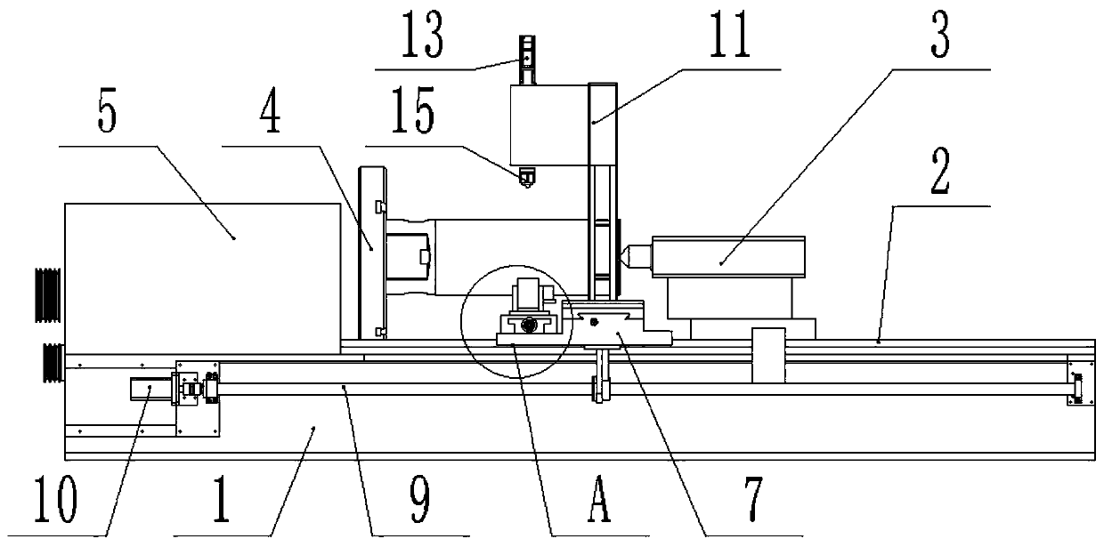
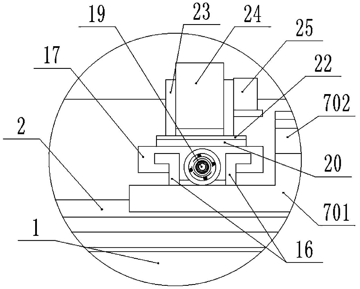
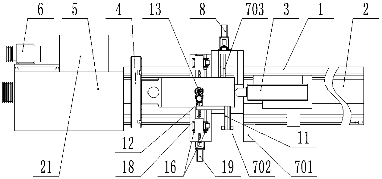
[0035] like Figure 1-4A high-speed laser cladding machine tool shown includes a base 1, a control box 21 is provided on one side of the base 1, and the control box 21 is electrically connected to a first servo motor 6, a second servo motor 8, a third servo motor The servo motor 10, the fourth servo motor 13, the fifth servo motor 19, the grinding mechanism and the laser cladding head 15, the base 1 is provided with a slide rail 2, and the slide rail 2 is slidably provided with a rotary thimble 3, The precise control of the rotary thimble 3 is realized through the electric telescopic rod, and the chuck 4 matched with the rotary thimble 3 is installed on one end of the slide rail 2, and the workpiece is fixed through the cooperation of the chuck 4 and the rotary thimble 3, A reduction box 5 is instal...


PUM


Abstract

The invention discloses a high-speed laser cladding processing machine tool, and belongs to the technical field of machine tool processing. The high-speed laser cladding processing machine tool comprises a base, wherein a slide rail is arranged on the base; a rotary ejector pin is arranged on the slide rail in a sliding mode; one end of the slide rail is equipped with a chuck; the chuck is connected to a reduction box; the reduction box is connected to a first servo motor; a first slide table is mounted on the slide rail; one end of the first slide table is connected to a second servo motor, and the other end of the first slide table is connected to a first lead screw; the first lead screw is connected to a third servo motor; a bracket is fixedly mounted on the first slide table; a secondslide table is mounted on the bracket; one end of the second slide table is equipped with a fourth servo motor; a laser cladding head bracket for mounting a laser cladding head is fixedly arranged onthe second slide table; a small slide rail is arranged on the first slide table at one side of the laser cladding head bracket; two movable bases are mounted on the small slide rail in the sliding mode; the movable bases are connected to a two-way lead screw; the two-way lead screw is connected to a fifth servo motor; a grinding mechanism is mounted on the movable bases; and a damping mechanism ismounted between the movable bases and the grinding mechanism.

Description

technical field [0001] The invention relates to the technical field of machine tool processing, in particular to a high-speed laser cladding processing machine tool and a processing method. Background technique [0002] Laser cladding refers to placing the selected coating material on the surface of the substrate to be clad in different ways, and then irradiating it with laser to melt it and a thin layer on the surface of the substrate at the same time, and form a very low dilution after rapid solidification. The surface coating that is metallurgically combined with the substrate is a process method that significantly improves the wear resistance, corrosion resistance, heat resistance, oxidation resistance and electrical properties of the base surface, so as to achieve the purpose of surface modification or repair, which not only satisfies the specific needs of the material surface Performance requirements, but also save a lot of precious elements. Compared with surfacing, ...

Claims


Application Information

Patent Timeline
Patent Type & Authority Applications(China)
IPC IPC(8): B24B1/00B24B27/00B24B41/06B24B47/22B24B47/12B24B41/02B24B41/00C23C24/10
CPCB24B1/00B24B27/0076B24B41/007B24B41/02B24B41/06B24B47/12B24B47/22C23C24/10
Inventor 陈启升别世清姜长升张红梅马中涛
Owner 山东高锻机械有限公司
Learn More