
Numerical control drill double relief angle blade milling machine

A sharpening machine and drill bit technology, which is applied in the direction of twist drills, drilling tool accessories, drilling/drilling equipment, etc., can solve the problems of grinding wheel breakage, easy accidents, and large size error of the back angle of the drill bit, and achieve complete shape correction. Consistent, good equipment safety, low labor intensity

Active Publication Date: 2010-07-14
NANJING CHENGUANG GRP
View PDF0 Cites 16 Cited by
  • Summary
  • Abstract
  • Description
  • Claims
  • Application Information

AI Technical Summary

Problems solved by technology

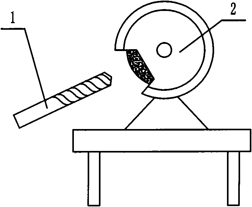
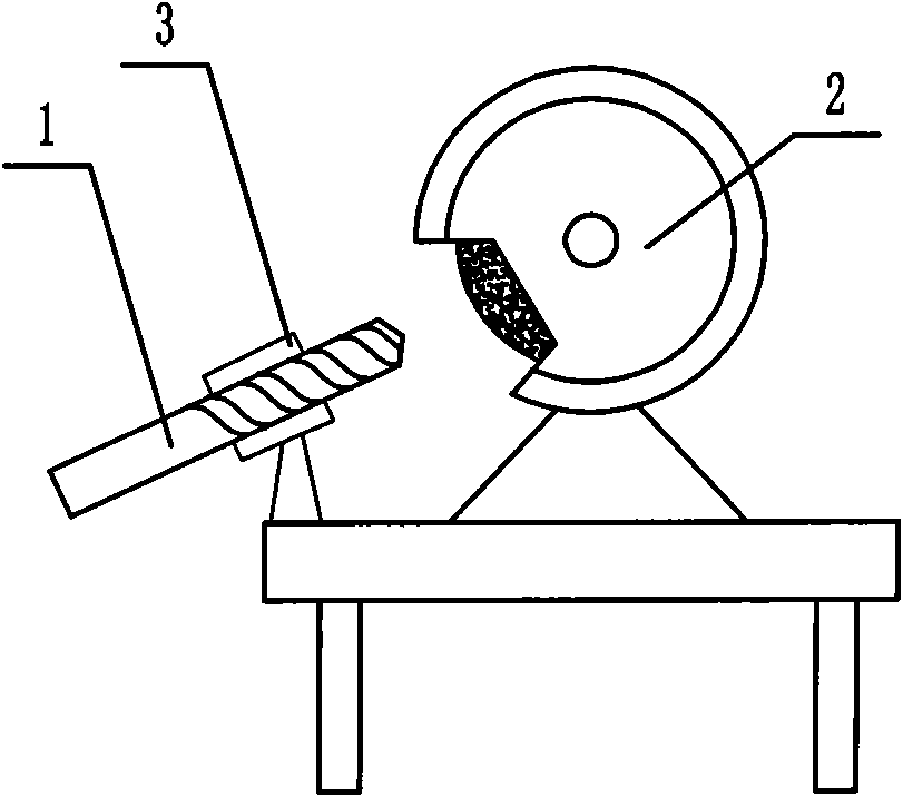
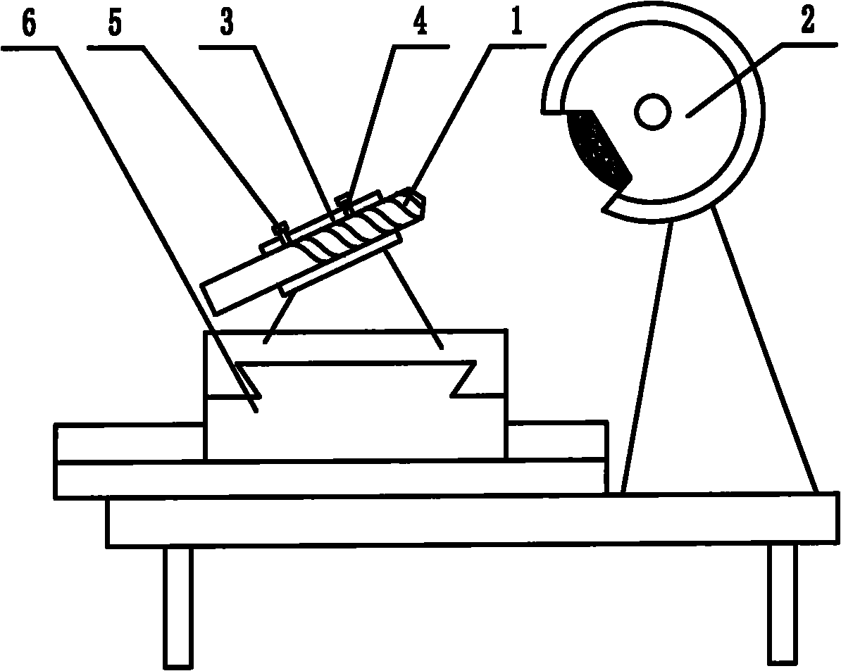
At present, there are mainly the following three methods for the double relief angle processing of drill bits in my country: the first is that the operator uses the hand-held drill bit 1 to directly grind on the grinding wheel 2, and uses manual feeding, see figure 1 , the second is to set the guide sleeve 3 at a fixed position in front of the grinding wheel 2, insert the drill bit 1 into the guide sleeve 3, and then use manual feeding, see figure 2 ; The third is to add indexing pin 4 and locking screw 5 on the basis of the original guide sleeve 3, and set the guide sleeve 3 on the movable cross support plate 6 for positioning, see image 3 , although this method has positioning, but because it is still a manual operation, the feed speed and the length of the grinding time are inconsistent, and the size error of the back angle of the drill bit is large.
Moreover, in the existing processing method, the operator is operating on the front of the grinding wheel, and the phenomenon of sand bursting occurs from time to time. If the force is too large when feeding, the grinding wheel is broken, which will cause a safety accident.
Therefore, the existing double relief angle processing methods of drill bits have disadvantages such as low precision, low efficiency, poor consistency, and accidents.

Method used


Image

  • Numerical control drill double relief angle blade milling machine
  • Numerical control drill double relief angle blade milling machine
  • Numerical control drill double relief angle blade milling machine

Examples


Embodiment Construction

[0015] see Figure 4 to Figure 5 , The present invention has a frame 10, an electric control cabinet 11, a hydraulic device 12, an operation panel 13, and a lubrication device 14. It also has a grinding wheel device 20, a grinding wheel feed device 30, a grinding wheel compensation device 40, a grinding wheel dressing device 50, and automatic feeding The device 60, the drill bit clamping device 70, the chuck feed device 80, and the detection sensor 91 for indexing and positioning the processed drill.

[0016] The grinding wheel device 20 is arranged on the frame and includes a grinding wheel frame 21, a grinding wheel 22 and a driving motor 23 for driving the grinding wheel to rotate. The grinding wheel frame is fixedly installed on the frame, and the grinding wheel and the grinding wheel frame are adjustablely connected. The grinding wheel feeding device 30 is arranged on the grinding wheel frame, and includes a grinding wheel feeding cylinder 31 that drives the grinding wheel 2...


PUM


Abstract

The invention relates to a numerical control machine device, in particular to a numerical control machine device carrying out grinding processing on a drill. The invention aims to provide a numerical control drill double relief angle blade milling machine. The device can carry out grinding processing on relief angles of the drills with different specifications and has high processing precision, high efficiency, good consistency and good safety. The numerical control drill double relief angle blade milling machine is provided with a stander, an electrical cabinet, a hydraulic device, an operation panel and a lubricating device. The stander is provided with a grinding wheel unit. The grinding wheel unit comprises a grinding wheel rack fixed on the stander, a grinding wheel in adjustable connection with the grinding wheel rack and a driving motor driving the grinding wheel to rotate. The grinding wheel rack is provided with a grinding wheel feeding device. The grinding wheel feeding device is provided with a grinding wheel feeding cylinder driving the grinding wheel to move. The front side of the grinding wheel rack on the stander is provided with an automatic loading device. The automatic loading device comprises a hopper storing processed components, a hopper cylinder driving the hopper, a trough for operating the components, a feeding rod and a feeding cylinder driving the feeding rod. A drill clamping device is arranged on the right side of the automatic loading device on the stander and comprises a chuck, a servo motor driving the chuck to rotate, a clamping cylinder and a brake cylinder. The lower part of the drill clamping device is provided with a chuck feeding device. The chuck feeding device comprises a guide rail which supports the drill clamping device and provides moving guide for the drill clamping device and a chuck feeding cylinder driving the drill clamping device to move.

Description

Technical field [0001] The invention relates to a numerical control machine tool equipment, in particular to a numerical control machine tool equipment for grinding a drill bit. Background technique [0002] As we all know, drills, milling cutters, taps, reamers, etc. are the most common and commonly used tools in the machinery industry. These tools will not meet their requirements due to wear after a period of use. Because there is no suitable grinder, some of them are thrown away and cause waste, and some of them are manually ground, which is labor-intensive. Especially for twist drills, according to European and American standards, the drills currently produced in my country are semi-finished products. At present, the drills produced by Chinese tool manufacturers require users to sharpen and grind the back angle on the grinder. However, European and American countries require drills to be purchased. Can be used. Therefore, drills exported to European and American countries mu...

Claims


Application Information

Patent Timeline
Patent Type & Authority Applications(China)
IPC IPC(8): B24B3/32
Inventor 严伟张立兵彭晓东张婷婷陆振利李仁文
Owner NANJING CHENGUANG GRP
Learn More