
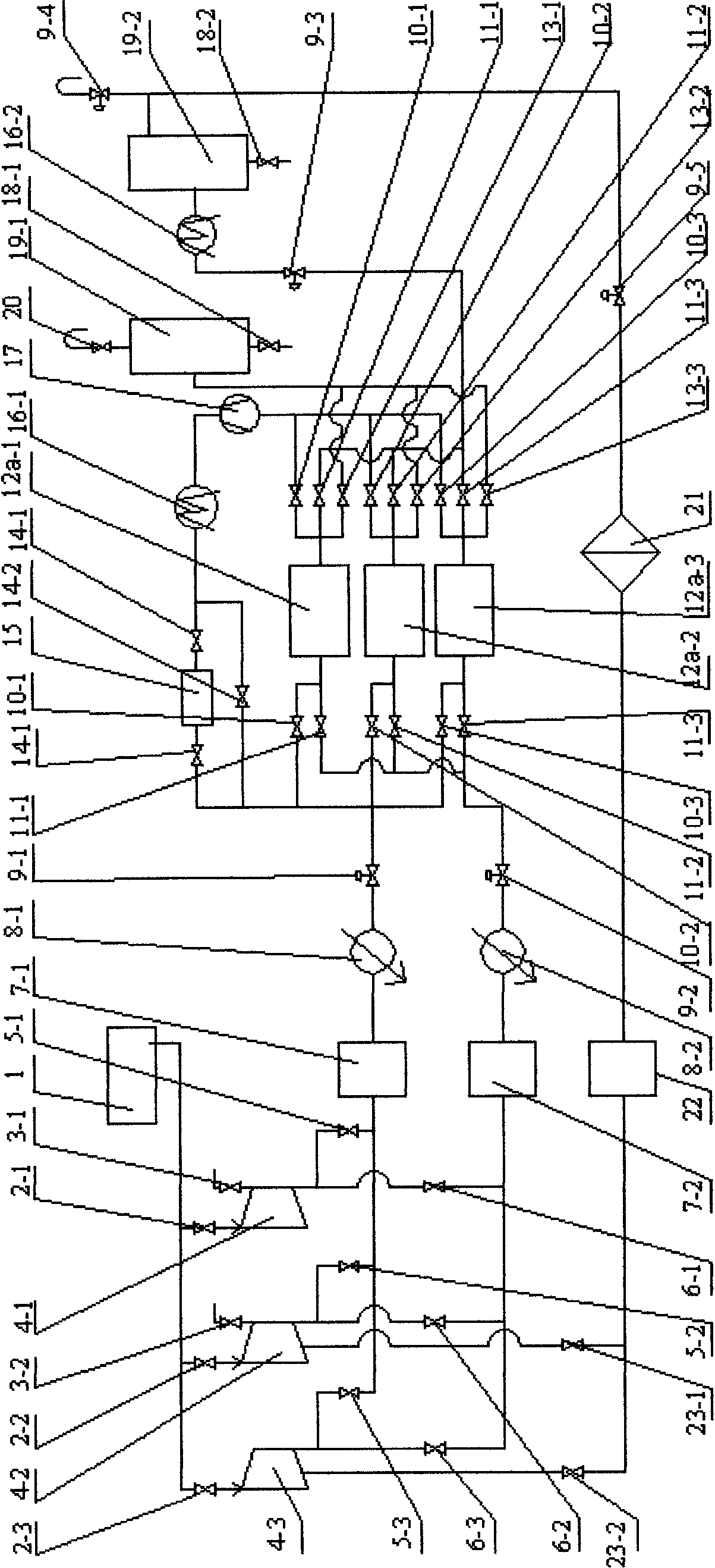
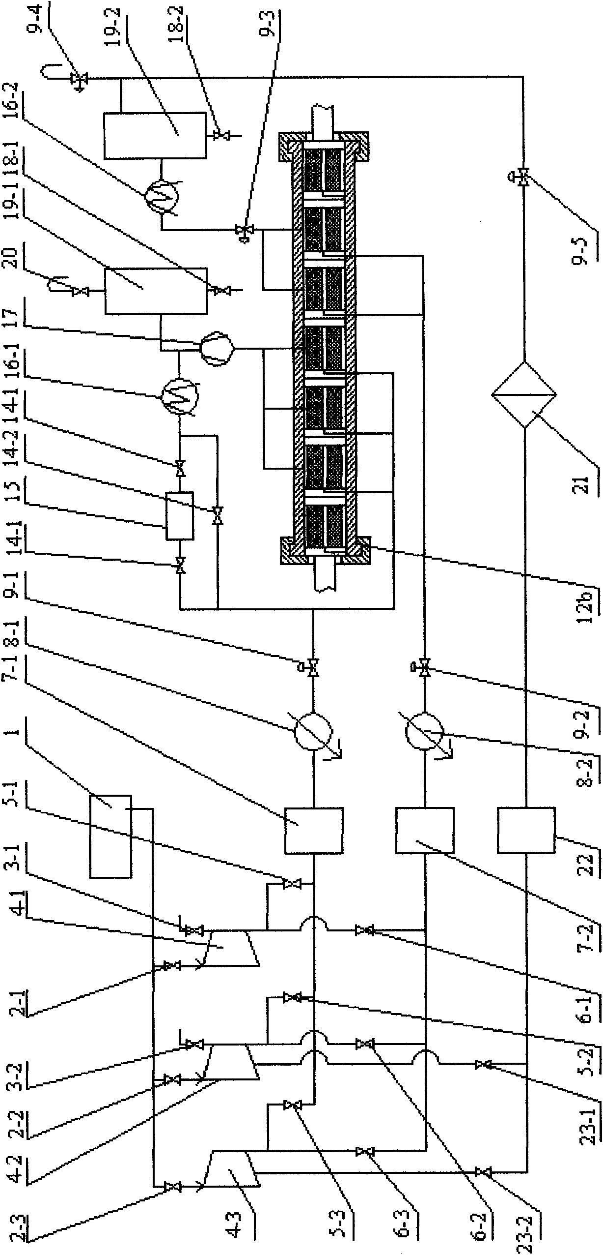
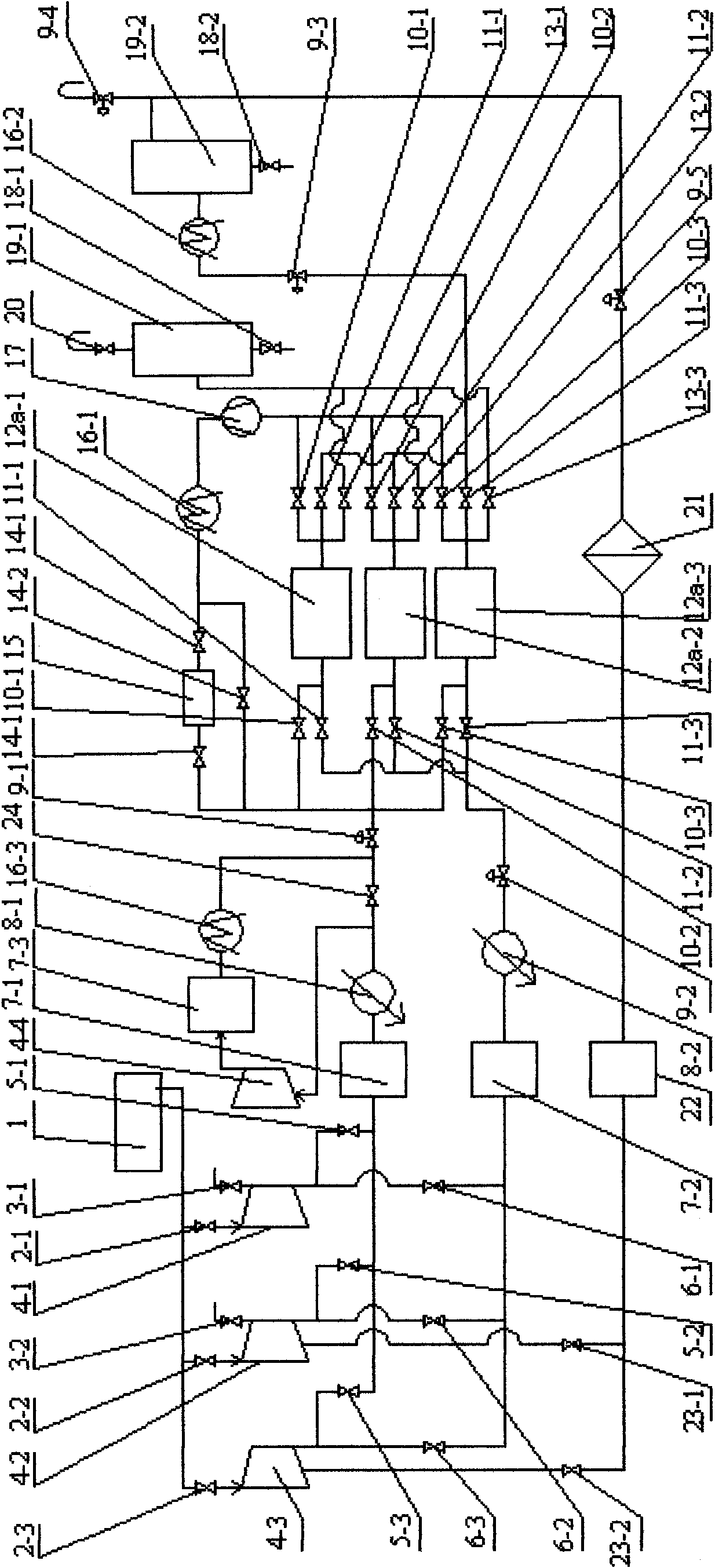
Process flow of supercritical carbon dioxide dyeing combining with urea production system

A carbon dioxide and production system technology, applied in dyeing, textile material treatment, liquid/gas/steam treatment of a certain length of textile materials, etc., can solve the problems of high operation, maintenance and management costs, small equipment scale, and poor manufacturing technology Mature and other issues, to achieve the effect of reducing one-time equipment investment, improving production efficiency, and reducing operation

Inactive Publication Date: 2010-07-14
SHANDONG UNIV
View PDF8 Cites 4 Cited by
  • Summary
  • Abstract
  • Description
  • Claims
  • Application Information

AI Technical Summary

Problems solved by technology

[0005] At present, the supercritical fluid dyeing process must be built separately, and the various equipment required need to be specially purchased. The carbon dioxide gas in operation also needs to be purchased separately. The one-time investment in fixed assets is large, and the operation, maintenance and management costs are very high. It has greatly hindered the industrialization and application of supercritical carbon dioxide dyeing technology
In particular, this type of process is often due to the small scale of equipment and immature manufacturing technology, which further restricts the development and application of supercritical carbon dioxide dyeing technology.

Method used


Image

  • Process flow of supercritical carbon dioxide dyeing combining with urea production system
  • Process flow of supercritical carbon dioxide dyeing combining with urea production system
  • Process flow of supercritical carbon dioxide dyeing combining with urea production system

Examples


Embodiment 1

[0032] Embodiment 1. According to the process conditions of supercritical carbon dioxide dyeing, through different combinations of system operation carbon dioxide compressors, spare carbon dioxide compressors and newly added carbon dioxide compressors in urea production, the dyeing / cleaning pressure does not exceed the pressure of the urea production system. Implementation of supercritical carbon dioxide dyeing process:

[0033] For example, the total amount of carbon dioxide in a urea production system is 594Nm 3 / min, urea production gas 475Nm 3 / min, excess carbon dioxide is 119Nm 3 / min, the system uses 4M32-125 / 210 carbon dioxide compressor, its exhaust pressure is 21MPa, and the rated carbon dioxide displacement of a single unit is 125Nm 3 / min, four open and two standby, the sum of the excess carbon dioxide displacement of the system running compressors is 25Nm 3 / min.

[0034](1) The implementation process of the supercritical carbon dioxide dyeing process formed b...

Embodiment 2

[0055] Embodiment 2: According to the process conditions of supercritical carbon dioxide dyeing, different combinations of operating the carbon dioxide compressor in the urea production system, the system spare carbon dioxide compressor and the newly added carbon dioxide compressor are used, and the carbon dioxide booster compressor is added to form an extraction Implementation of supercritical carbon dioxide extraction process with pressure exceeding urea production system pressure:

[0056] Such as image 3 , Figure 4 As shown, the connection mode of each process unit before the dyeing heater 8-1 and after the dyeing regulating valve 9-1 is exactly the same as the various processes (1) to (7) in Embodiment 1; the difference is that the dyeing heater 8 After -1, it is divided into two roads, and one road directly reaches the dyeing regulating valve 9-1 through the high and low pressure cut-off valve 24 opened between the dyeing heater 8-1 and the dyeing regulating valve 9-1...


PUM


Abstract

The invention relates to equipment and process for chemical industry and dyeing, in particular to a process flow of supercritical carbon dioxide dyeing combining with a urea production system. In the flow, the combination of an original or a new carbon-dioxide compressor in the urea production system and a fluid source compressor set of the supercritical carbon dioxide dyeing, or the single running or stand-by or new carbon-dioxide compressor in the urea production system, or one of the combinations including the combination of the running carbon-dioxide compressor and the stand-by carbon-dioxide compressor in the system, the combination of the running carbon-dioxide compressor and the new carbon-dioxide compressor in the system, the combination of the stand-by carbon-dioxide compressor and the new carbon-dioxide compressor in the system and the combination of the running carbon-dioxide compressor, the stand-by carbon-dioxide compressor and the new carbon-dioxide compressor in the system is selected; the selected compressor set is utilized to compress surplus carbon dioxide in the urea production system; the compressed carbon dioxide is taken as a supercritical fluid source of the supercritical carbon dioxide dyeing system and is inputted to a supercritical carbon dioxide dyeing system to complete a process flow of the supercritical carbon dioxide dyeing. In the process flow, the resources of the surplus carbon dioxide, surplus production capacity and a large number of human resources are utilized fully, the production efficiency of urea production enterprises is improved, disposable equipment investment of dyeing production is reduced, the running, maintenance and management cost of the dyeing production are reduced, and energy conservation, emission reduction and consumption reduction are realized.

Description

1. Technical field [0001] The invention relates to chemical engineering and dyeing equipment and technology, in particular to a supercritical carbon dioxide dyeing process combined with a urea production system. 2. Background technology [0002] Existing supercritical carbon dioxide dyeing is a whole process of independent operation. This process usually consists of a supercritical carbon dioxide generation unit, a dye dissolving and fiber or fabric dyeing unit, a dyed fiber or fabric cleaning unit, and a carbon dioxide separation and recovery unit. For the continuous dyeing process, the dyeing unit is divided into a dyeing section and a washing section. The fiber or fabric in the dyeing machine can automatically complete the movement from the dyeing section to the washing section. The dyeing unit and the washing unit are independent and continuous operating units. For the intermittent dyeing process, the dyeing machine does not have two stages of dyeing and washing, and th...

Claims


Application Information

Patent Timeline
IPC IPC(8): D06B9/00D06B23/20D06P1/94
CPCD06B5/16
Inventor 王威强王杰胡德栋郭建章曲延鹏刘燕
Owner SHANDONG UNIV
Learn More