Cylinder cooling water channel structure and engine

A cylinder cooling and water channel technology, which is used in engine components, machines/engines, engine cooling, etc., can solve the problems of high temperature outside the cylinder and poor cooling effect, to ensure performance and reliability, improve stiffness, and uniform temperature. The effect of distribution

Inactive Publication Date: 2010-07-14
GUANGXI YUCHAI MASCH CO LTD
View PDF0 Cites 6 Cited by
  • Summary
  • Abstract
  • Description
  • Claims
  • Application Information

AI Technical Summary

Problems solved by technology

[0003] Aiming at the deficiencies of the prior art, the present invention provides a cylinder cooling waterway structure and an engine using the cylinder cooling waterway struc...

Method used


Image

  • Cylinder cooling water channel structure and engine
  • Cylinder cooling water channel structure and engine
  • Cylinder cooling water channel structure and engine

Examples


Embodiment Construction

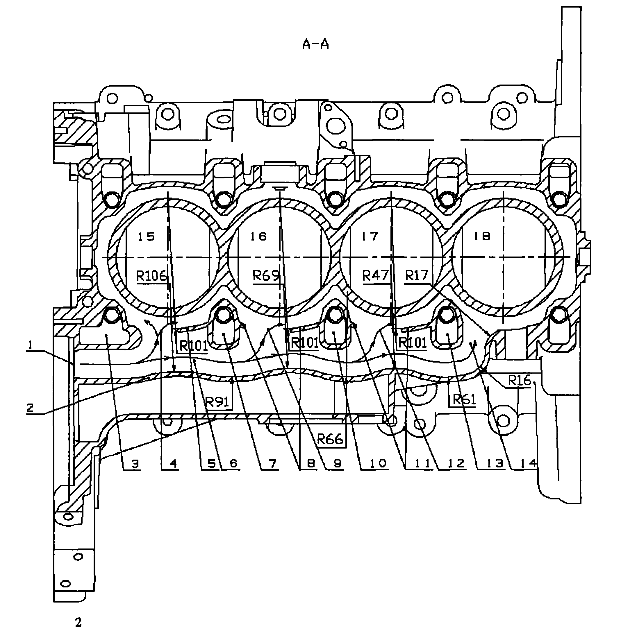
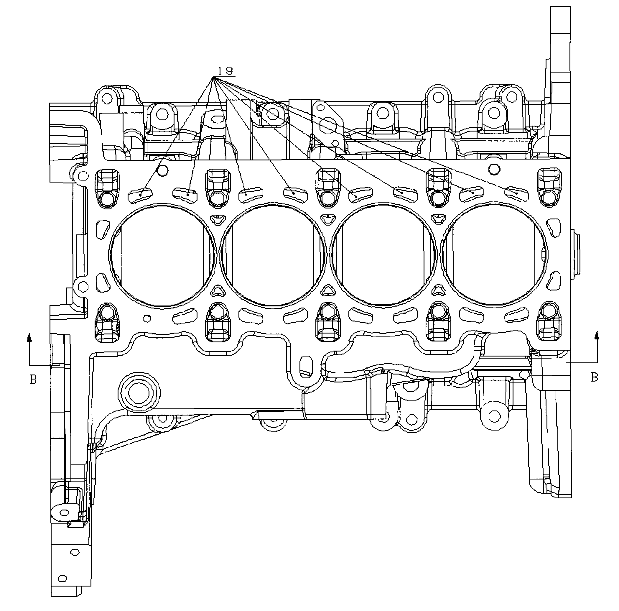
[0017] The invention provides a cross-flow cooling water channel structure that makes the outside of all cylinders have a more uniform temperature distribution. The side of the water pump of the cylinder body is provided with a liquid distribution channel with a corrugated water channel wall, and the cooling liquid provided by the water pump directly enters the liquid distribution channel. , the cooling liquid is evenly distributed to each cylinder through the guide port on the partition plate set between the corrugated water channel wall and the liquid distribution channel and each cylinder.

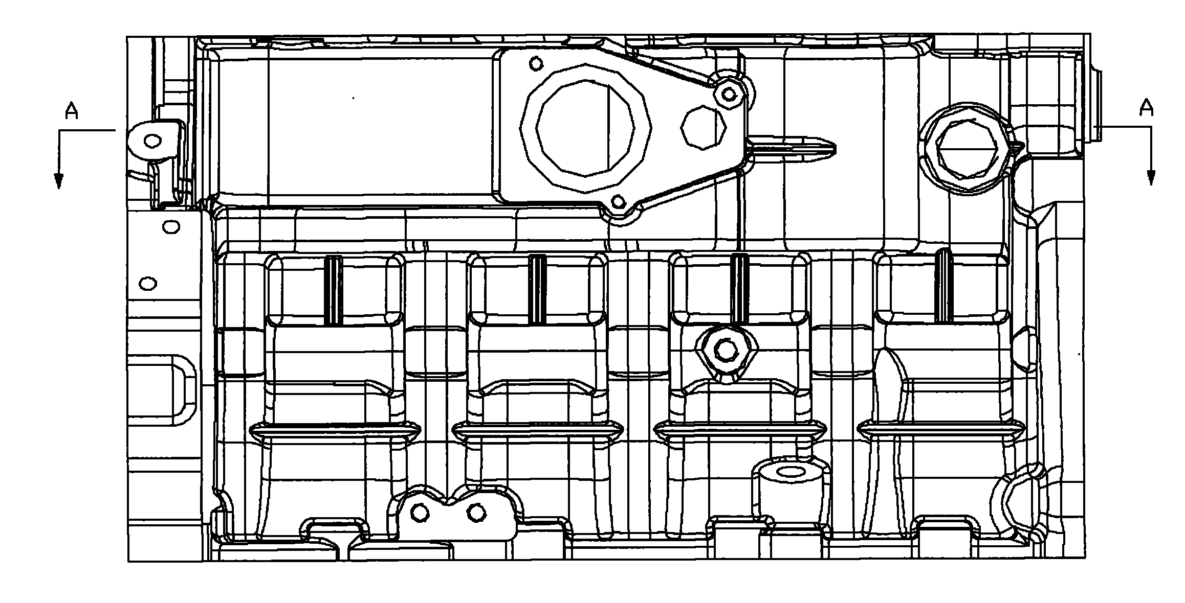
[0018] The structure of a cylinder cooling channel of a four-cylinder diesel engine according to an embodiment of the present invention will be described in detail below in conjunction with the accompanying drawings.

[0019] The invention discloses a cylinder cooling channel structure, such as figure 2 , Figure 4 As shown, it includes coolant inlet 1; liquid distribution channel 6; ...


PUM


Abstract

The invention discloses a cylinder cooling water channel structure and an engine. The cooling structure comprises cylinders, a cooling liquid inlet, a wave-shaped water channel wall, a liquid distribution channel, baffles and diversion ports. The liquid distribution channel is arranged on the side of the water pump of a cylinder body. The cooling liquid inlet is communicated with the liquid distribution channel. The baffles with the diversion ports are arranged on the side of the cylinder tightening bolt between two cylinders and on the side of an oil and gas ventilation hole. The wave-shaped water channel wall is arranged at a position corresponding to the diversion port. The invention provides the transverse flow cooling water channel structure which can enable the temperature on the external side of all cylinders to be more evenly distributed, solves the problems of the traditional longitudinal flow structure that the temperature on the external side of the cylinder far away from cooling liquid is high and the cooling effect is not good, and can enable the temperature on the external side of all cylinders to be more evenly distributed. Moreover, the design of the liquid distribution channel, the baffles and the diversion ports can improve the rigidity of the cylinder body, so the performance and the reliability of the entire engine are effectively guaranteed.

Description

technical field [0001] The invention relates to a cooling water passage structure and an engine, in particular to an engine cylinder cooling water passage structure and an engine using the cylinder cooling water passage structure. Background technique [0002] At present, the cooling cycle of the engine is that the coolant enters the cylinder block through the water pump, and the coolant flows through each cylinder in turn to cool the cylinders. This traditional longitudinal flow structure often makes the temperature of the rear cylinders higher than that of the front cylinders, and the cooling effect will be inconsistent. As a result, the work uniformity of each cylinder is reduced, thereby affecting the performance and reliability of the whole machine. Contents of the invention [0003] Aiming at the deficiencies of the prior art, the present invention provides a cylinder cooling waterway structure and an engine using the cylinder cooling waterway structure to solve the ...

Claims


Application Information

Patent Timeline
IPC IPC(8): F02F1/14F01P3/02
Inventor 沈捷李金印韩义勇王利民
Owner GUANGXI YUCHAI MASCH CO LTD
Why Eureka
Try Eureka