
Testing device for high temperature thermal shock resistance of refractory material and application method thereof

A technology of thermal shock resistance and refractory material, applied in the direction of measuring device, analysis material, strength characteristics, etc., can solve the problems of manual operation, many cycles, inaccurate time control, etc., to achieve enhanced automation, accurate test results, The effect of a high degree of automation

Inactive Publication Date: 2010-07-14
WUHAN UNIV OF SCI & TECH
View PDF5 Cites 16 Cited by
  • Summary
  • Abstract
  • Description
  • Claims
  • Application Information

AI Technical Summary

Problems solved by technology

[0005] First, when the furnace door is opened, the temperature inside the furnace radiates outward, and the manual operation environment is poor;
[0006] The second is to manually control the time of rapid heating, rapid cooling, and placing in the air. Due to the large number of cycles, the operator is prone to fatigue, and each time period is prone to inaccurate time control. Time forgetting and delays occur from time to time, which directly affects the accuracy of the results;
[0007] The third is to manually record the number of tests, which is easy to forget or record too much;
[0008] Fourth, because the test is a simple repeated cycle test, the time of the test is very long, and manual operation is laborious and time-consuming;
[0009] Fifth, the damage rate of the test surface of sample 14 is manually judged, and the error is large

Method used


Image

  • Testing device for high temperature thermal shock resistance of refractory material and application method thereof
  • Testing device for high temperature thermal shock resistance of refractory material and application method thereof
  • Testing device for high temperature thermal shock resistance of refractory material and application method thereof

Examples


Embodiment Construction

[0071] Below in conjunction with accompanying drawing and specific embodiment, the present invention is further described, not limiting the scope of protection:

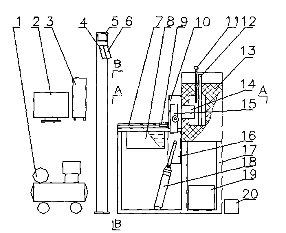
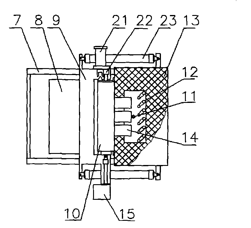
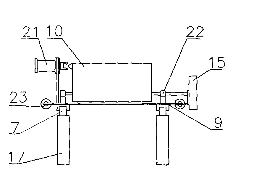
[0072] A test device for high temperature thermal shock resistance of a refractory material and a use method thereof. assumed figure 1 The left side is the front, and the right side is the back. The device as figure 1 As shown: the heating furnace 13 is installed on the rear half of the bracket 17, the heating furnace 13 is equipped with a heating element 12 and a thermocouple 11, a cooling water tank 8 is arranged in front of the furnace door 16 of the heating furnace 13, and the cooling water tank 8 is installed on the bracket 17 Below the front half of the furnace door 16 and the front of the cooling water tank 8, a door frame 5 is provided, and 3 to 6 camera lights 4 and 3 to 6 cameras 6 are installed on the top of the door frame 5.

[0073] The fixed ends of two furnace door cylinders 18 are respectively hing...


PUM

PropertyMeasurementUnit
Thicknessaaaaaaaaaa

Abstract

The invention relates to a testing device for high temperature thermal shock resistance of a refractory material and an application method thereof. The invention adopts the technical scheme that a heating body 12 and a thermocouple 11 are installed in a heating furnace 13, a cooling water tank 8, a slide rail 7 and a camera 6 are arranged at the front of the heating furnace, a sliding frame 9 is arranged on the slide rail 7, a brick clamping device 10 is installed on the sliding frame 9, a sample 14 is placed in the brick clamping device 10, an original image of the measured surface of the sample 14 is collected through the camera 6, the sample 14 is sent into the heating furnace 13 for heating and heat preservation after the heating and the heat preservation of the heating furnace 13, water cooling is carried out for the sample 14 after being discharged from the furnace, then the sample 14 is placed in the air for cooling, the image of the measured surface of the sample 14 after testing is collected through the camera 6, the area and the breakage rate of the measured surface of the sample 14 are computed, and the high temperature thermal shock resistance of the sample 14 is measured according to the rule of YB / T 376.1-1995. The testing device has the characteristics of high automation degree, accurate test result and high testing efficiency.

Description

technical field [0001] The invention belongs to a test device for refractory materials, in particular to a test device for high-temperature thermal shock resistance of refractory materials and a use method thereof. Background technique [0002] The high temperature industry served by refractory materials has very harsh working conditions. Refractory materials are often subjected to rapid cooling and rapid heating during use. In this case, thermal stress will be generated inside the refractory material. When the thermal stress is greater than the internal bonding strength of the refractory material, the refractory material will be damaged. , The manifestation of this damage is mainly cracking and peeling. Thermal shock damage is one of the important factors that determine the service life of refractory materials. The development of new high thermal shock refractory materials and engineering refractory materials need to evaluate their thermal shock stability, so thermal shock...

Claims


Application Information

Patent Timeline
IPC IPC(8): G01N3/60G01N3/06
Inventor 葛山尹玉成刘志强祝洪喜蔡鄂汉
Owner WUHAN UNIV OF SCI & TECH
Learn More