
Automatic crack detection system and method for medium-thick plate

An automatic and internal detection technology, applied in the direction of material analysis, measuring devices, and instruments using sound waves/ultrasonic waves/infrasonic waves, can solve problems such as low detection efficiency, affecting plate shape adaptability, production line productivity bottlenecks, etc., to reduce steel plate pauses The number of times, the effect of improving efficiency and practicality, and improving adaptability

Active Publication Date: 2014-03-05
ALLRISING BEIJING TECH
View PDF7 Cites 0 Cited by
  • Summary
  • Abstract
  • Description
  • Claims
  • Application Information

AI Technical Summary

Problems solved by technology

The obvious disadvantage of this solution is that the detection efficiency is low (usually it takes at least 4 minutes to detect a steel plate), especially when the detection system is installed on the production line, it will become the productivity bottleneck of the production line
In addition, the internal inspection of this inspection process uses two sets of cross-compensation methods to achieve 100% flaw detection. Due to the different specifications of the steel plates, it is impossible to guarantee the same detection blind area on the non-reference side of the steel plate with different specifications (maximum increase to 1 internal inspection unit) width, such as 100mm), which increases the detection range requirements of the non-reference side detector (right side detector), thus expanding the mechanical structure of the non-reference side detection trolley, which in turn affects the adaptability of the equipment to the board shape, and affects the reliability of the equipment. Practicality

Method used

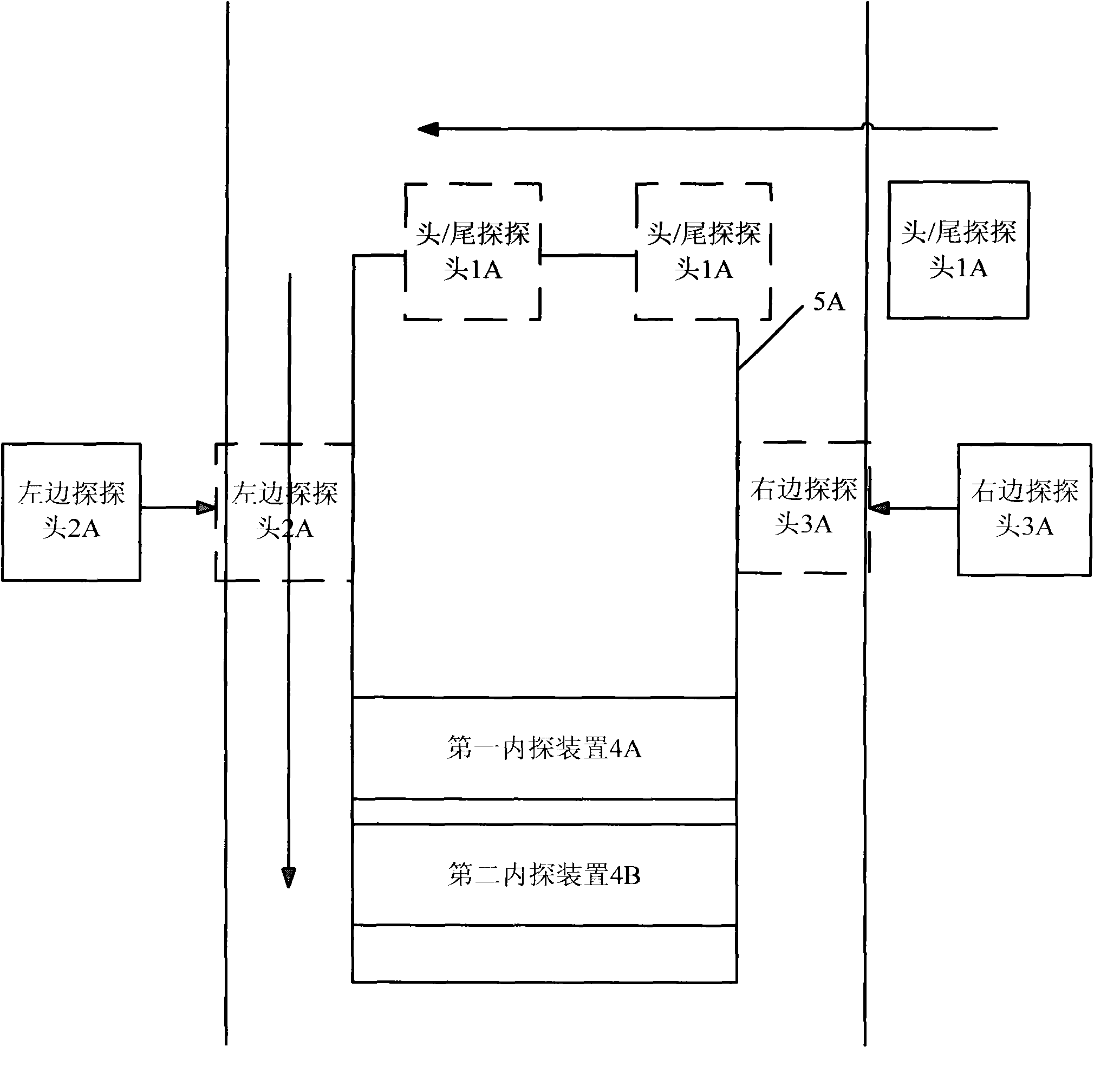

Image

  • Automatic crack detection system and method for medium-thick plate
  • Automatic crack detection system and method for medium-thick plate
  • Automatic crack detection system and method for medium-thick plate

Examples


Embodiment Construction

[0033] The implementation of a system and method for improving the automatic flaw detection of medium and thick plates according to the present invention will be described in detail below in conjunction with the accompanying drawings.

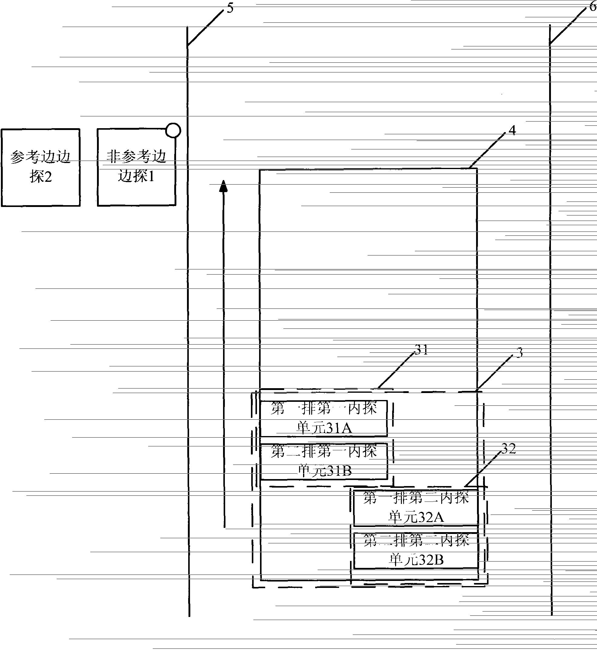
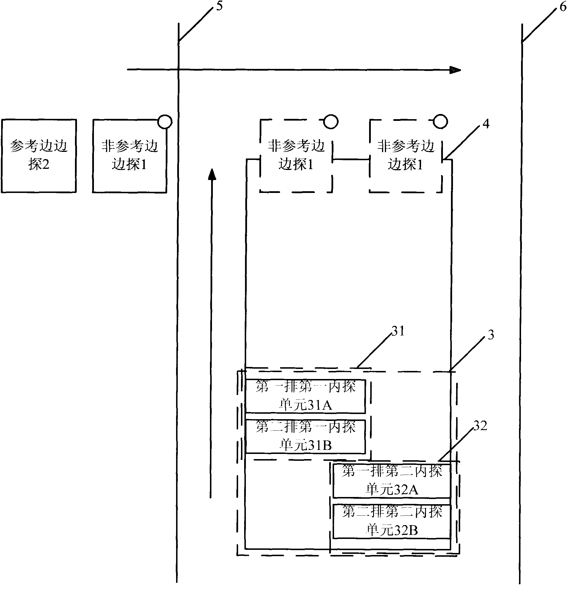
[0034] see figure 2 , the present invention improves the automatic flaw detection of medium and thick plates, including: non-reference edge detection 1 , reference edge detection 2 and internal detection device 3 . The starting position of non-reference side edge detection 1 is located on the side of reference side 5, responsible for head flaw detection, non-reference edge flaw detection and tail flaw detection. The starting position of reference edge detector 2 is located on the same side as reference edge 5 and non-reference edge detector 1, and is responsible for reference edge flaw detection. The internal detection device 3 is in charge of the flaw detection of the steel plate 4 and consists of two groups of internal detection units: a fi...


PUM


Abstract

The invention relates to an automatic crack detection system and a method for medium-thick plates. The automatic crack detection system comprises an automatic crack detection control device, a steel plate movement control device, a first inner detection unit, a second inner detection unit and an inner detection unit movement control device. The automatic crack detection control device orders the steel plate movement control device to move a steel plate and orders the inner detection unit movement control device to control the first inner detection unit and the second inner detection unit to conduct inner detection to the steel plate. The automatic crack detection system additionally comprises a non-reference side detection unit, a reference side detection unit, a non-reference side detection unit movement control device and a reference side detection unit movement control device. The automatic crack detection control device orders the non-reference side detection unit movement control device and the reference side detection unit movement control device to control the non-reference side detection unit and the reference side detection unit to conduct head crack detection, side part crack detection and tail part crack detection to the steel plate. Thereby, the invention has the advantages that the crack detection efficiency and the practicability are improved.

Description

technical field [0001] The invention relates to the field of non-destructive testing, in particular to a novel automatic flaw detection system and method for medium and thick plates. Background technique [0002] The development history of the world's steel industry shows that the production level of medium and thick steel plates is an important symbol of the level of a country's steel industry. For ordinary medium-thick steel plates, the quality of the steel plates can be guaranteed to meet the application requirements by strictly controlling the metallurgical process, and steel mills usually conduct random inspections on product quality; while for shipbuilding plates, offshore platform plates, pipeline plates, boiler plates, pressure vessel plates, Special medium-thick steel plates such as bridge plates, automobile girder plates, weather-resistant plates, high-strength structural plates, and construction machinery plates, while ensuring production quality, comprehensive fl...

Claims


Application Information

Patent Timeline
Patent Type & Authority Patents(China)
IPC IPC(8): G01N29/265
Inventor 郭大勇阙开良陈斌
Owner ALLRISING BEIJING TECH
Learn More