Single-loop pulse regulating and controlling method and device of pseudo continuous mode switch power supply

A mode switch and pulse regulation technology, applied in the direction of conversion equipment without intermediate conversion to AC, can solve the problems of not being suitable for high-power occasions, achieve good anti-interference ability, broaden the application range, and overcome the complexity of detection and processing feedback Effect

Inactive Publication Date: 2010-07-14
SOUTHWEST JIAOTONG UNIV
View PDF0 Cites 5 Cited by
  • Summary
  • Abstract
  • Description
  • Claims
  • Application Information

AI Technical Summary

Problems solved by technology

Its disadvantage is that it can only be used to control switching converters operating in the inductor current discontinuous mode (DCM), and the working range is limited by the critical condition of the inductor current, so it is not suitable for high-power applications

Method used


Image

  • Single-loop pulse regulating and controlling method and device of pseudo continuous mode switch power supply
  • Single-loop pulse regulating and controlling method and device of pseudo continuous mode switch power supply
  • Single-loop pulse regulating and controlling method and device of pseudo continuous mode switch power supply

Examples


Embodiment 1

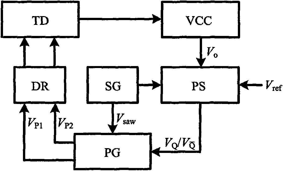
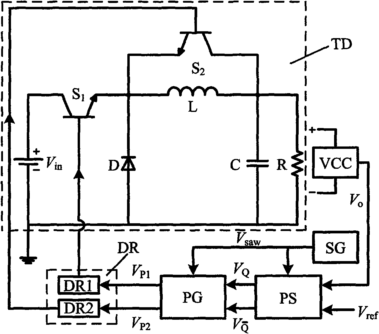
[0041] figure 1 It is shown that a specific embodiment of the present invention is a control method of a switching power supply, and its specific method is:

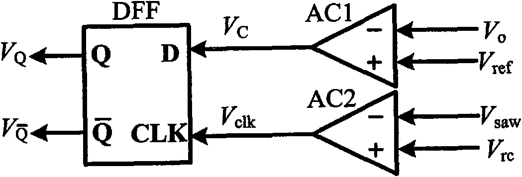
[0042] At the beginning of each switching cycle, the controller according to the output voltage V of the switching converter TD o with reference voltage V ref The relationship between selects the effective control pulse in the switching period, so as to realize the control of the switching converter TD. Its control pulse selection rule is: if V o below V ref , using the control pulse P H1 and P H2 Separately control the switching tube S in the pseudo-continuous switching converter 1 and S 2 ; Conversely, if V o higher than V ref , using the control pulse P L1 and P L2 Separately control the switching tube S 1 and S 2 .

[0043] The controller generates a control pulse P H1 and P H2 The method is: at the beginning of a certain switching cycle t 0 moment, the control pulse P H1 From low level to high leve...

Embodiment 2

[0058] Figure 7 It is shown that this example is basically the same as the first example, except that the converter TD of the switching power supply controlled by this example is a Boost converter.

Embodiment 3

[0060] Figure 8 It is shown that this example is basically the same as the first example, except that the converter TD of the switching power supply controlled by this example is a Buck-Boost converter.

[0061] The method of the present invention can be realized with analog device or digital device conveniently; Except the switching power supply that can be used for the converter in the above embodiment to form, also can be used for Cuk converter, BIFRED converter, flyback converter, half-bridge converter , full-bridge converter and other power circuits to form a switching power supply.


PUM


Abstract

The invention discloses a single-loop pulse regulating and controlling method and device of a switch power supply working in a pseudo continuous mode. The method is as follows: during the starting time of each on-off cycle, the effective control pulse in the on-off cycle is selected according to relation between the output voltage Vo and reference voltage Vref voltage of a switching converter. The selection rules of the control pulse are as follows: if Vo is less than Vref, the control pulse PH1 and PH2 are adopted to separately control the switching tube S1 and S2 in the pseudo continuous switching converter; and if Vo is more than Vref, the control pulse PL1 and PL2 are adopted to separately control the switching tube S1 and S2. The duty-cycle and time sequence of each control pulse are both preset and fixed values. The method can be used to control the high power switching converter working in the pseudo continuous mode, the control technology is easy and practical, the stability and anti-interference ability are good, the working range of the converter is wide, the dynamic performance is good and the method is applicable to switching converters with various topological structures.

Description

technical field [0001] The invention relates to a control method and device for a switching power supply. Background technique [0002] Most electrical equipment (such as computers, communication equipment, electric machinery, industrial control equipment, high-efficiency lighting devices, etc.) require general power (such as mains power) to be converted to meet their use needs. In recent years, switching power supply technology has been a hot spot in the field of electrical engineering applications and research. [0003] The switching power supply is mainly composed of two parts, the DC-DC converter and the controller. DC-DC converters are used for power conversion, and are generally composed of switching devices and rectification and filtering circuits. The circuit structures include Buck, Boost, flyback, and full bridge. The controller is used to detect the working state of the converter circuit, and generate a control pulse signal to control the switching device in the...

Claims


Application Information

Patent Timeline
Patent Type & Authority Applications(China)
IPC IPC(8): H02M3/10
Inventor 秦明许建平牟清波王金平
Owner SOUTHWEST JIAOTONG UNIV
Why Eureka
Try Eureka