Switched reluctance motor variable-angle PI control method, controller and speed adjusting system

A switched reluctance motor and controller technology, which is applied in control systems, AC motor control, electronic commutation motor control, etc., can solve the problems of poor resistance of switched reluctance motors, slow system dynamic response, and high actual average speed. To achieve the effect of simple and reliable control method, strong versatility, and easy promotion

Active Publication Date: 2017-08-15
HUNAN UNIV
View PDF7 Cites 5 Cited by
  • Summary
  • Abstract
  • Description
  • Claims
  • Application Information

AI Technical Summary

Problems solved by technology

But the traditional speed PI controller has such a problem: when the given steering is constant, the on-angle and off-angle of each phase are fixed, and the motor can only output the torque in the same direction as the given steering, so that when the speed difference is less than zero At this time, the motor can only track the given speed by free stop, resulting in slow dynamic response of the system and the actual average speed is higher than the given speed, which makes the resistance of the switched reluctance motor to the interference opposite to the given direction is very poor. And the motor does not have load capacity when the given direction of rotation is opposite to the direction of the load

Method used


Image

  • Switched reluctance motor variable-angle PI control method, controller and speed adjusting system
  • Switched reluctance motor variable-angle PI control method, controller and speed adjusting system
  • Switched reluctance motor variable-angle PI control method, controller and speed adjusting system

Examples


Embodiment 1

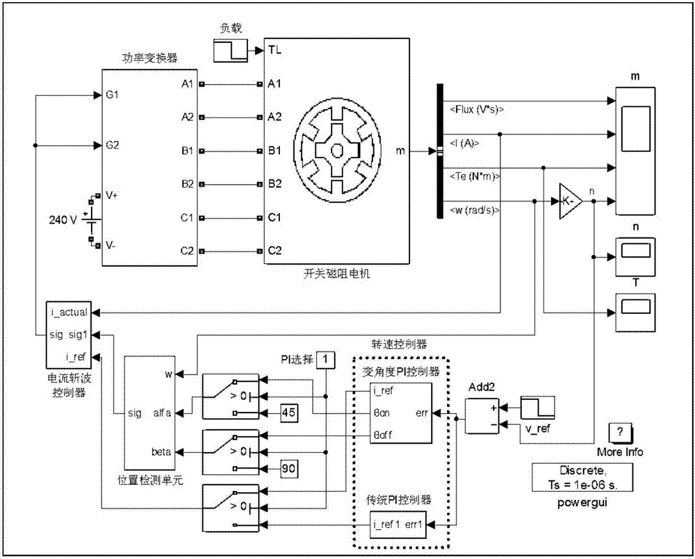
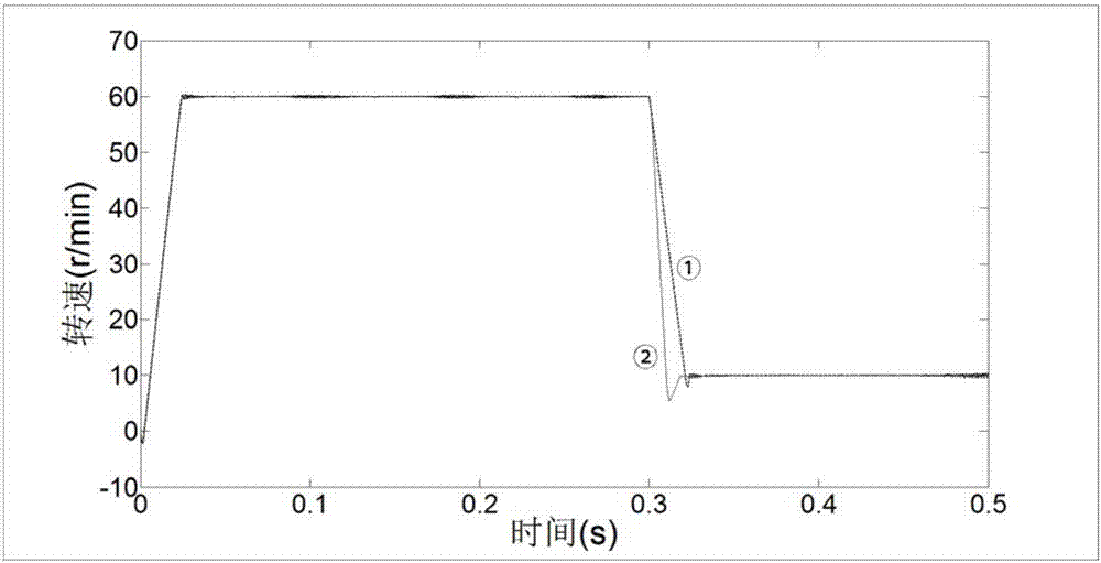
[0026] based on figure 1The simulink simulation model shown is used to test the control effect under the traditional PI control and the control of the present invention and collect data to fit the curve. The speed curves of the traditional PI control and the control of the present invention when the given speed changes stepwise from 60rpm to 10rpm are as follows image 3 As shown, the corresponding torque curve is shown as Figure 4 As shown, ① in the figure is the traditional PI control; ② is the control of the present invention. image 3 In the above, before the given speed step changes, the two methods achieve almost the same control effect, but after the given speed is stepped down, under the traditional PI control, it takes 31ms to reach the new steady state, while in this Under the inventive PI control, the new steady state was reached after only 18 ms.

[0027] The speed curves of the traditional PI control method and this method when the steady-state load at 60rpm c...


PUM


Abstract

The invention provides a switched reluctance motor variable-angle PI control method, a switched reluctance motor variable-angle PI controller and a switched reluctance motor speed adjusting system. The switched reluctance motor variable-angle PI control method comprises the steps of: regarding an absolute value of an output signal of a traditional rotary speed PI controller as a reference current of a current chopping controller, switching turn-on and turn-off angles of each phase according to positive and negative output of the traditional rotary speed PI controller, placing the turn-on and turn-off angles of each phase in a forward torque region when the output is negative, and outputting forward torque by a motor; otherwise, turning over the turn-on and turn-off angles to a backward torque region by taking theta=theta<r / 2> as a symmetry axis, and outputting backward torque by the motor. According to the switched reluctance motor variable-angle PI control method, the switched reluctance motor variable-angle PI controller and the switched reluctance motor speed adjusting system, the switched reluctance motor can output torque opposite to a given rotary direction when the given rotary direction is fixed, the dynamic response speed in the cases of sudden reduction of a given rotary speed and sudden unloading when the given rotary direction is fixed is accelerated, the switched reluctance motor has a loading capacity under the situation that the given rotary direction is opposite to a load direction, and the control method is simple and reliable, high in universality and easy to popularize.

Description

technical field [0001] The invention relates to the field of motor control, in particular to a variable-angle PI control method, controller and speed regulating system of a switched reluctance motor. Background technique [0002] Switched reluctance motor is a new type of electromechanical integration motor, which has the advantages of simple and firm structure, reliable operation, good speed regulation performance, low manufacturing cost, suitable for high speed and harsh environment operation, etc. These excellent characteristics make it an electrical One of the research topics in the field of transmission, it has been applied in the fields of motor drive systems, fans, water pumps, aerospace and other fields, showing its strong market competitiveness. A suitable control strategy is the basis for realizing the good performance of the switched reluctance motor. The double salient pole structure of the stator and rotor of the switched reluctance motor and its highly nonlinea...

Claims


Application Information

Patent Timeline
Patent Type & Authority Applications(China)
IPC IPC(8): H02P6/08H02P6/00H02P25/08
Inventor 李孟秋蔡辉沈仕其王辉罗德荣
Owner HUNAN UNIV
Why Eureka
Try Eureka