Method, equipment and system for reporting buffer zone state
A buffer state and buffer technology, applied in the field of communication, can solve the problem of being unable to distinguish the buffer state of VOIP services, etc., and achieve the effect of saving uplink scheduling signaling and avoiding waste of resources
- Summary
- Abstract
- Description
- Claims
- Application Information
AI Technical Summary
Problems solved by technology
Method used
Image

Examples
Embodiment 1
[0027] Embodiment 1 of the present invention provides a method for reporting buffer status, including: UE sending buffer status and characteristic information, wherein the characteristic information is used to indicate that the buffer status corresponds to VOIP service.
[0028] Further, the characteristic information may be a dedicated logical channel group identifier LCG ID indicating that the buffer state corresponds to the VOIP service, or a logical channel identifier LC ID.
[0029] In this embodiment, when the UE reports the buffer state, it also provides the service characteristic information corresponding to the buffer state, so that the network node such as eNB can identify the service corresponding to the buffer state as a VOIP service according to the characteristic information, and can Further perform resource scheduling for VOIP services, save uplink scheduling signaling, and avoid resource waste.
Embodiment 2
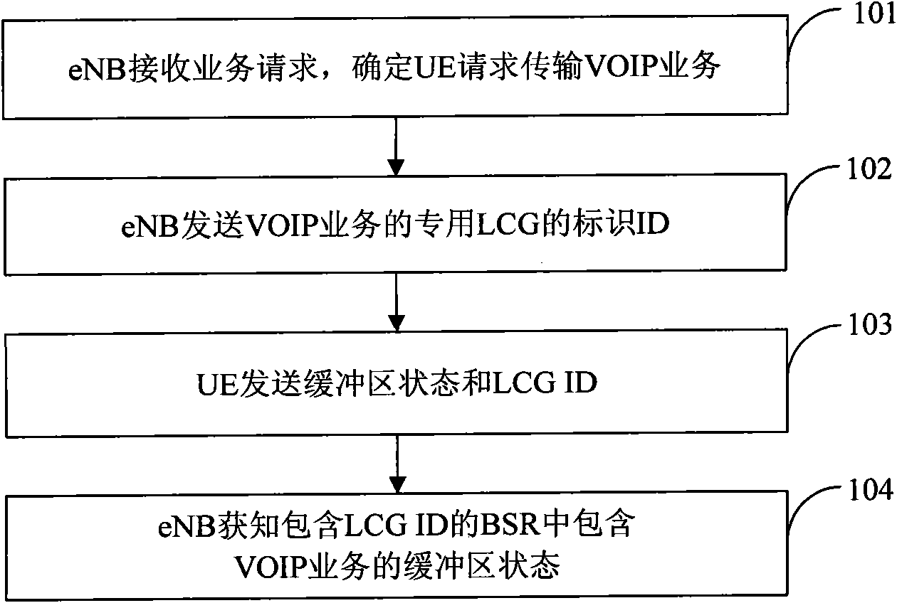
[0031] see figure 1 , the embodiment of the present invention provides a method for reporting buffer status, which may include the following steps:
[0032] 101: The eNB receives the service request sent by the UE or the core network, and determines that the service requested by the UE to be transmitted is a VOIP service according to the QCI (Quality Control Indication, Quality Control Indication) in the request;
[0033] 102: The eNB configures a dedicated LCG for the UE's VOIP service, and sends DRB (Data Radio Bearer, Data Radio Bearer) configuration information for the VOIP service, where the configuration information includes the identification ID of the dedicated LCG;
[0034] In this step, the eNB notifies the UE by sending the LCG ID: the LCG is used to send the buffer state of the VOIP service; correspondingly, after receiving the LCG ID, the UE takes it as an indication that the buffer state corresponds to the VOIP service. In this step, it may be assumed that the L...
Embodiment 3
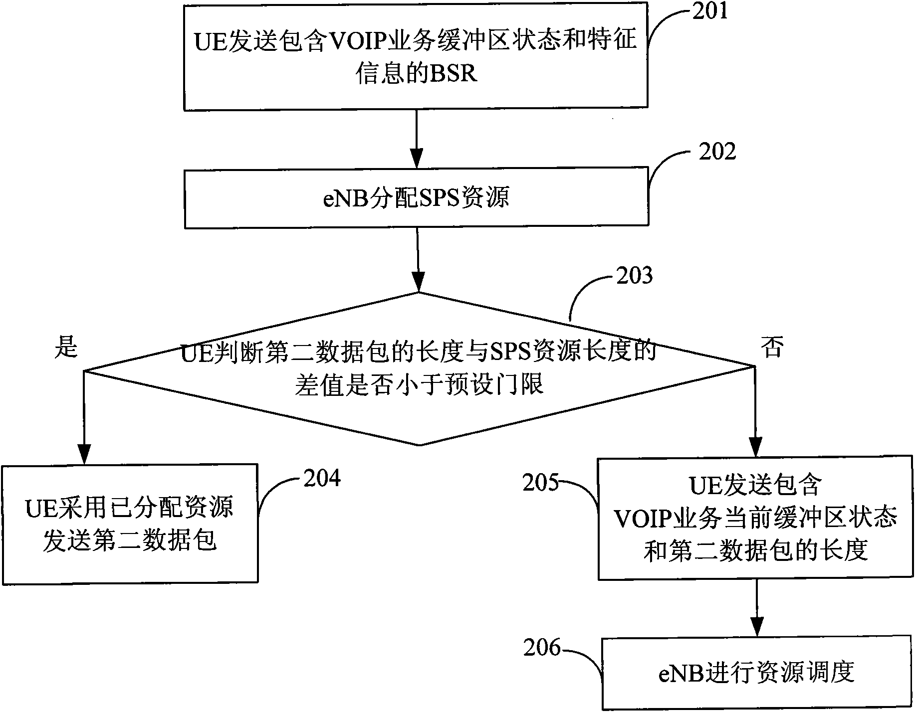
[0042] Embodiment 3 of the present invention provides a method for reporting the buffer status, including: sending the buffer status when the data length of the VOIP service arriving in the buffer reaches the length of the semi-static scheduling resource.
[0043] Further, the UE may calculate the difference between the received VOIP service data length and the length of the semi-persistent scheduling resource, and if the difference is greater than a preset threshold, the UE sends the buffer status, where the preset threshold may be greater than or equal to 0 .
[0044] In this embodiment, when a large amount of VOIP service data bursts, the UE acquires sufficient transmission resources in time, thereby ensuring timely data transmission, avoiding loss of VOIP service data, and improving VOIP service quality.
PUM
 Abstract
Description
Claims
Application Information
 - Generate Ideas
- Intellectual Property
- Life Sciences
- Materials
- Tech Scout
- Unparalleled Data Quality
- Higher Quality Content
- 60% Fewer Hallucinations
Browse by: Latest US Patents, China's latest patents, Technical Efficacy Thesaurus, Application Domain, Technology Topic, Popular Technical Reports.
© 2025 PatSnap. All rights reserved.Legal|Privacy policy|Modern Slavery Act Transparency Statement|Sitemap|About US| Contact US: help@patsnap.com