
Needle holder used for minimally invasive surgery intracavitary operation

A minimally invasive surgery and needle holder technology, applied in the field of medical devices, can solve the problems of difficult operation, increased surgical risk for patients, and inability to return to the same position, achieving simple and easy knotting of sutures, reducing surgical risks, and not easy to slide. shedding effect

Inactive Publication Date: 2010-07-21
SHANGHAI LINCHAO MEDICAL INSTR
View PDF4 Cites 1 Cited by
  • Summary
  • Abstract
  • Description
  • Claims
  • Application Information

AI Technical Summary

Problems solved by technology

[0003] Since the suturing of this operation is carried out in the cavity, it is very difficult to operate
However, the existing needle holders enter the wound straight up and down, and it is very difficult to control the direction of the thread. Therefore, it takes a lot of operation time to tie knots with the existing needle holders, resulting in prolonged operation time. More anesthesia, and the increase of anesthetics and the prolongation of operation time will increase the risk of surgery for patients
[0004] For the convenience of threading, there are commercially available needle holders with concave grooves, but the depth of the concave grooves is fixed and cannot be returned and flattened. It can only be used in open surgery and is not suitable for minimally invasive surgery. Use in intracavitary surgery

Method used


Image

  • Needle holder used for minimally invasive surgery intracavitary operation
  • Needle holder used for minimally invasive surgery intracavitary operation
  • Needle holder used for minimally invasive surgery intracavitary operation

Examples


Embodiment Construction

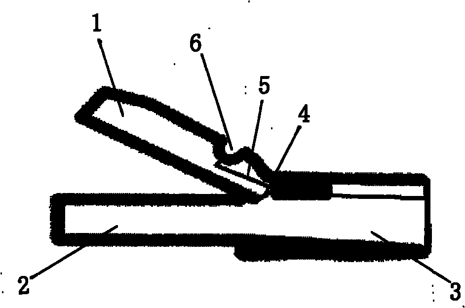
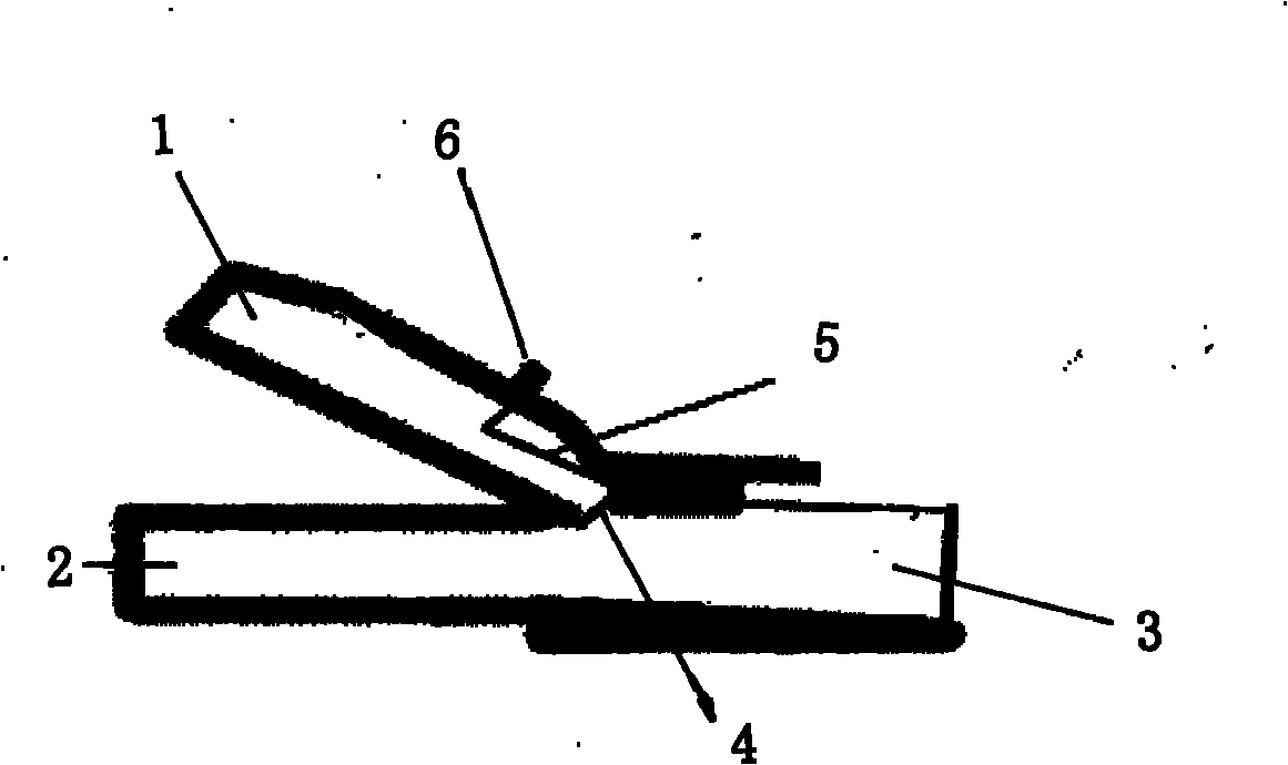
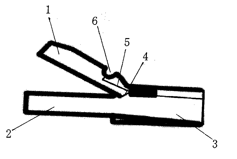
[0013] The structure of the needle holder of the present invention is shown in figure 1 and 2 , as can be seen from the figure, a needle holder for minimally invasive surgery in the cavity, including a handle 3, a chuck 1 and a chuck 2 connected to each other through a hinge point 4, is characterized in that: the chuck 1 and the chuck Any chuck outer side in the head 2 is equipped with a thread catcher 6, and the bottom of the thread catcher 6 is provided with a top core 5, and the Rui portion of the top core 5 can move up and down along the thread catcher 6.

[0014] Such as figure 1 As shown, the thread catcher 6 provided on the outer side of the chuck 1 is in the shape of a groove. When in use, when the handle 3 controls chuck 1 and chuck 2 to open, the top core 5 is at the bottom of the groove of the hook 6, so that the hook 6 can hook the thread; when the handle 3 controls chuck 1 and chuck 2 When closing, the chuck 2 moves the top core 5 upwards to eject the surgical ...


PUM


Abstract

The invention relates to a needle holder used for a minimally invasive surgery intracavitary operation, which comprises a handle and two clamping heads mutually connected by an articulated point, and is characterized in that the outer side of any one of the two clamping heads is provided with a thread catcher; the bottom of the thread catcher is provided with a top core; the end of the top core can move up and down along the thread catcher; and the thread catcher presents a groove shape and can also present a bulge shape. The invention has the advantages that since any one of the two clamping heads is provided with the thread catcher and hook an operation stitching thread by using the thread catcher, the operation stitching thread is not easy to slide and fall off, the moving direction of the operation stitching thread is easy to control and the clamping heads pass in and out freely when hooking the thread; moreover, since the bottom of the thread hooker is provided with the top core, and the operation stitching thread can be pushed out from the slot bottom of the groove-shaped thread catcher by the top of the top core or moves down together with the bulge-shaped thread catcher, the operation stitching thread can be conveniently separated from a groove or a bulge so that stitching and knotting are simpler and more convenient in a minimally invasive operation, thereby further shortening the operation time, reducing the dosage of anesthetic and lowering the operation risk for patients.

Description

technical field [0001] The invention relates to a medical device, in particular to a needle holder for minimally invasive surgery in a cavity. Background technique [0002] In minimally invasive surgery, especially in laparoscopic surgery, suturing is an important part of the operation. The usual way at present is to adopt the needle holder to clamp the needle with the suture thread, and perform the knotting suture operation under the laparoscope. [0003] Because the suturing of this operation is carried out in the cavity, it is very difficult to operate. However, the existing needle holders enter the wound straight up and down, and it is very difficult to control the direction of the thread. Therefore, it takes a lot of operation time to tie knots with the existing needle holders, resulting in prolonged operation time. More anesthesia, and the increase of anesthetics and the prolongation of operation time will increase the risk of operation for patients. [0004] For th...

Claims


Application Information

Patent Timeline
Patent Type & Authority Applications(China)
IPC IPC(8): A61B17/06
Inventor 林超段孝敏
Owner SHANGHAI LINCHAO MEDICAL INSTR
Learn More