
Control valve and valve with same

A technology for controlling valves and control valves, applied in valve operation/release devices, lift valves, valve details, etc., can solve problems affecting the vital economic interests of enterprises, institutions and properties, energy waste, and manual valves without energy-saving control.

Inactive Publication Date: 2010-07-21
HAILIN ENERGY TECH
View PDF0 Cites 6 Cited by
  • Summary
  • Abstract
  • Description
  • Claims
  • Application Information

AI Technical Summary

Problems solved by technology

However, the manual valve does not have the function of energy-saving control, and the opening and closing operation of the valve is non-recurring. Manual valves, therefore, for buildings that do not need heating throughout the day, it will inevitably cause a great waste of energy
For example, in offices or schools, it is usually only used for a certain period of time every day, most of the time there is no one, and the valve in front of the building is open all day during the heating period. In this way, there is energy waste during the time when no one is using it. problems that directly affect the vital economic interests of enterprises, institutions and properties
[0004] In view of this, it is urgent for HVAC practitioners to develop a controllable valve technology for use in front of buildings, so as to perform opening and closing operations according to actual needs, so as to adapt to the use of buildings that do not need all-day heating, and avoid unmanned Energy wasted during the time period of use

Method used


Image

  • Control valve and valve with same
  • Control valve and valve with same
  • Control valve and valve with same

Examples


Embodiment Construction

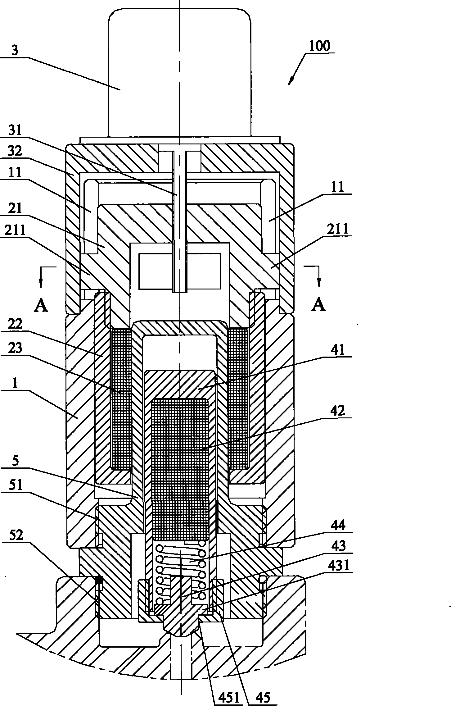
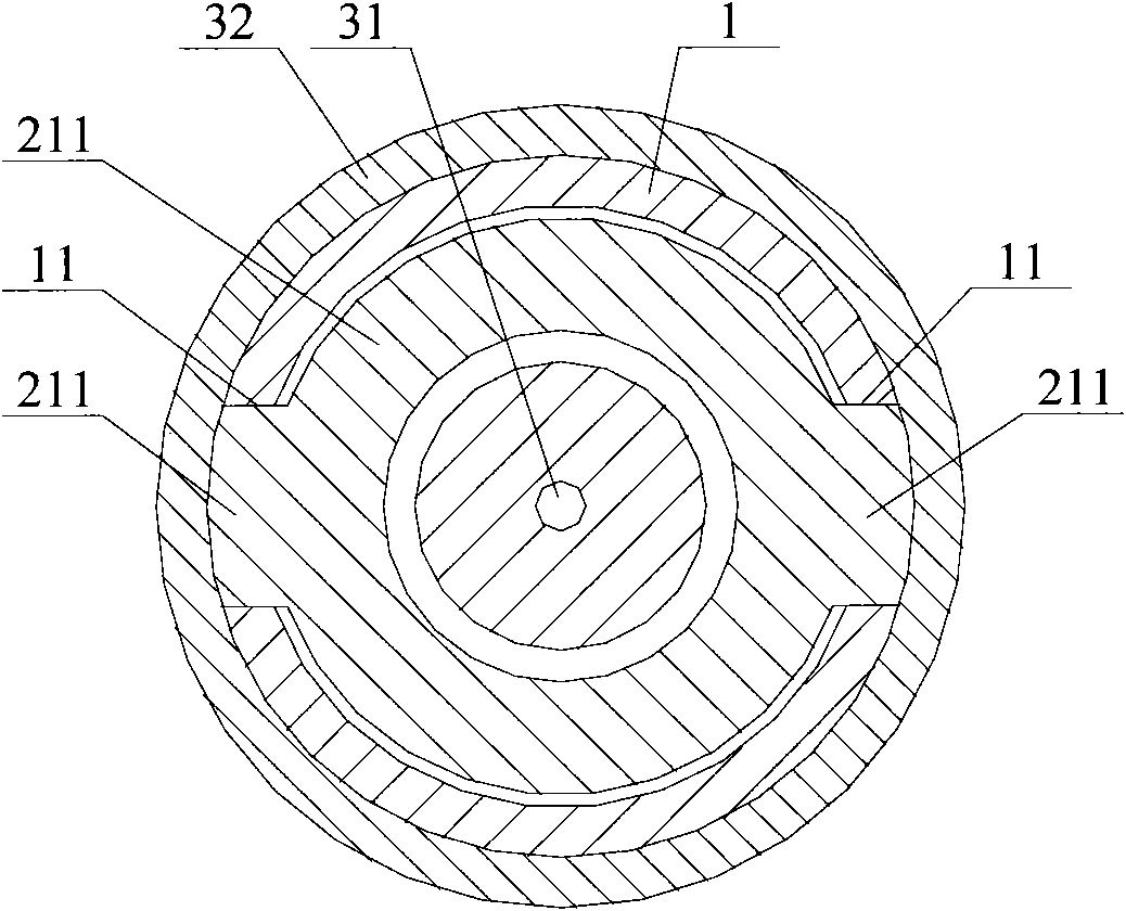
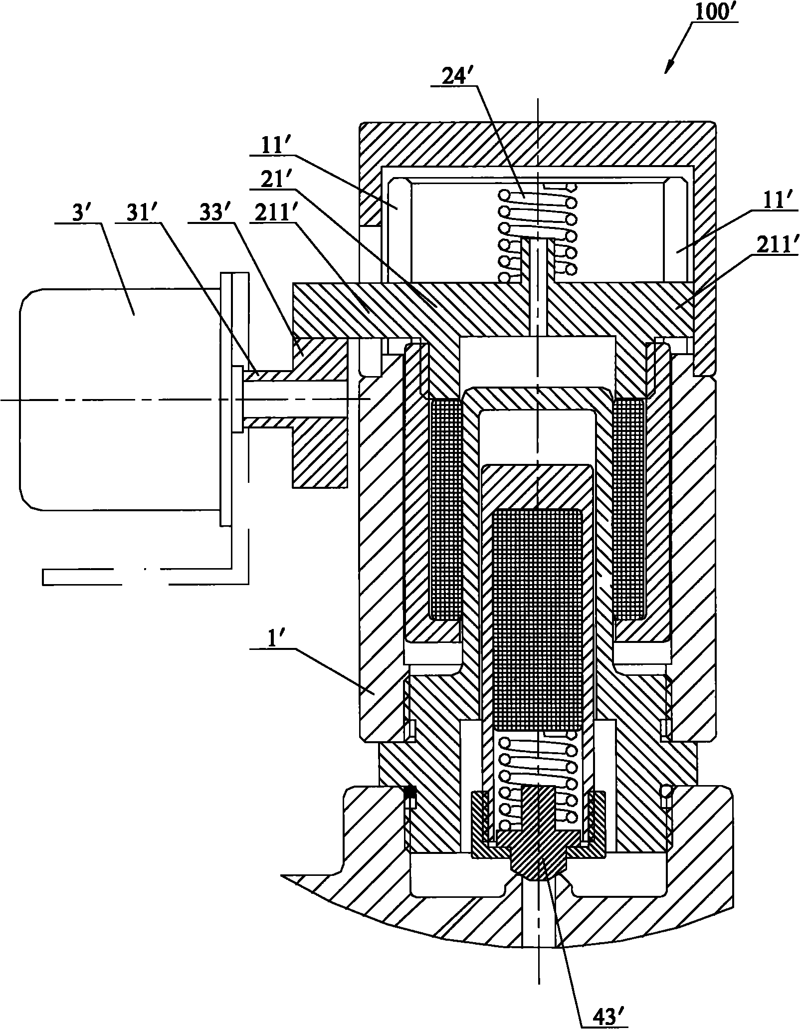
[0036] The core of the present invention is to provide a control valve, which is used to control the conduction state between the valve inlet and outlet, which mainly includes a valve body casing, a driving motor, a magnetic ring assembly and a magnetic core assembly; wherein, the driving motor is arranged on the valve The outer side of the body casing; the magnetic ring assembly is arranged in the valve body casing, the magnetic ring assembly is connected to the output shaft of the drive motor; the magnetic core assembly is nested inside the magnetic ring assembly, Its lower end is used to offset or separate from the flow channel between the inlet and outlet of the valve to realize the opening and closing of the valve; The magnetic core assembly moves axially, so as to resist or separate the magnetic core assembly from the valve flow channel. The invention utilizes the principle of magnetic coupling, and the movement of the magnetic ring assembly drives the magnetic core asse...


PUM


Abstract

The invention discloses a control valve. A magnetic ring component is arranged in a valve body sleeve and is connected with an output shaft of a driving motor; a magnetic core component is embedded on the inner side of the magnetic ring component, the lower end part of the magnetic core component is used for pressing against or separating from an overflow channel between a valve inlet and a valve outlet to realize the opening and closing of the valve; and under the action of the driving motor, the magnetic ring component moves in the sleeve axially and drives the magnetic core component to move axially. The invention also discloses a valve. A valve body is provided with a separation part which divides an inner chamber of the valve body into an inlet chamber and an outlet chamber; the side wall of the inlet chamber and the outlet chamber of the valve body at a position connected with the separation part is provided with a valve port; the opening end on the lower part of a valve cover is sealed and connected with the outer surface of the valve body at the periphery of the valve port; a piston is arranged in a valve cover accommodating chamber; the control valve is fixedly arranged on the valve cover; a second overflow channel is arranged between the outlet chamber of the valve body and the valve cover accommodating chamber above the piston; and the lower end part of the magnetic core component of the control valve is used for pressing against or separating from the second overflow channel.

Description

technical field [0001] The invention relates to a valve, in particular to a control valve and a valve with the control valve. Background technique [0002] At present, the world's energy reserves are limited, and human beings use a lot of energy everywhere in their lives, especially in the heating and cooling equipment of houses and offices. According to statistics, the current energy consumption for heating and heating accounts for about 10% of the total energy consumption of the whole society. Under the general environment of energy saving and emission reduction, energy-saving control of heating has become inevitable, so as to effectively alleviate the contradiction between energy shortage and social and economic development. [0003] In the building heating pipeline, the valve used in front of the building (referred to as the valve in front of the building) is set in the shaft in front of the building. At present, the existing valves in front of the building are all man...

Claims


Application Information

Patent Timeline
IPC IPC(8): F16K1/00F16K31/04
Inventor 李兆亮李海清
Owner HAILIN ENERGY TECH
Learn More