LED backlighting structure provided with converted light source and using free-form surface reflector

A technology of curved surface reflection and backlight structure, applied in the field of backlight systems, can solve the problems of limited thickness reduction and increased number of backlight systems, and achieve the effects of small thickness, large light source angle, and high overall light efficiency.

Inactive Publication Date: 2010-07-21
GUANGDONG REAL FAITH OPTO
View PDF16 Cites 10 Cited by
  • Summary
  • Abstract
  • Description
  • Claims
  • Application Information

AI Technical Summary

Problems solved by technology

[0006] In order to reduce the thickness of distributed LED direct-lit backlight, a technical solution is to increase the arrangement density of distributed LEDs, which can reduce the thickness of the system to a certain extent, but this technical solution will lead to a sharp increase in the number of LEDs , the number of LEDs used in 22-inch panels has exceeded 1,000, which will bring a series of problems such as light source consistency, reliability, and power drive; another method is to use secondary lenses to increase the light output angle of LEDs, which can also reduce the system Thickness, at present, free-form surface lenses with precise optical design have been applied to LED backlights, but when using secondary lenses to change the direction of light exit, due to the existence of total internal reflection, the light exit angle cannot be increased too much, and the backlight The degree of system thickness reduction is also limited, and there is still a certain gap compared with side-lit backlights

Method used


Image

  • LED backlighting structure provided with converted light source and using free-form surface reflector
  • LED backlighting structure provided with converted light source and using free-form surface reflector
  • LED backlighting structure provided with converted light source and using free-form surface reflector

Examples


Embodiment 1

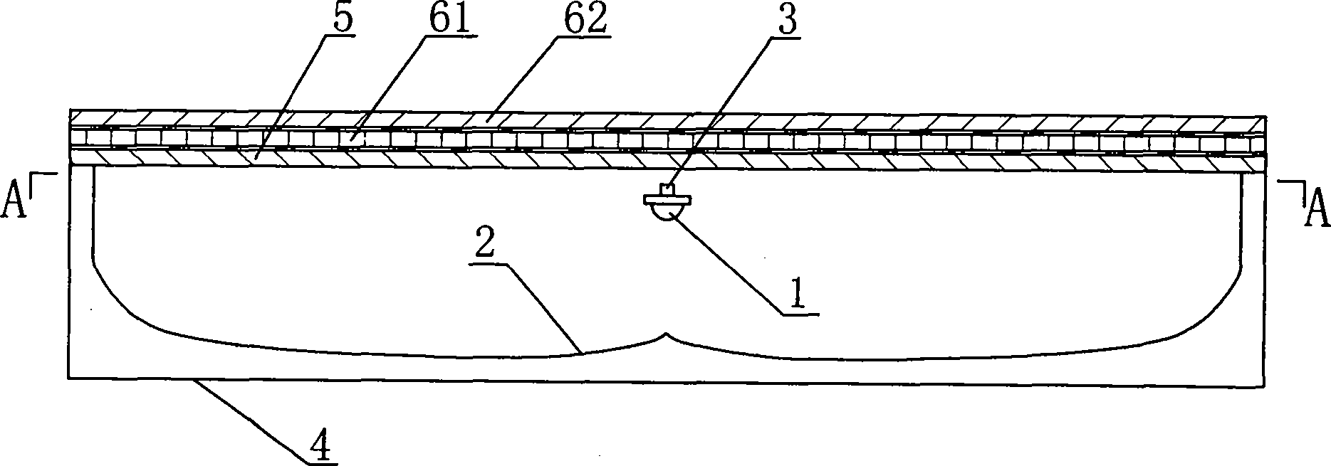
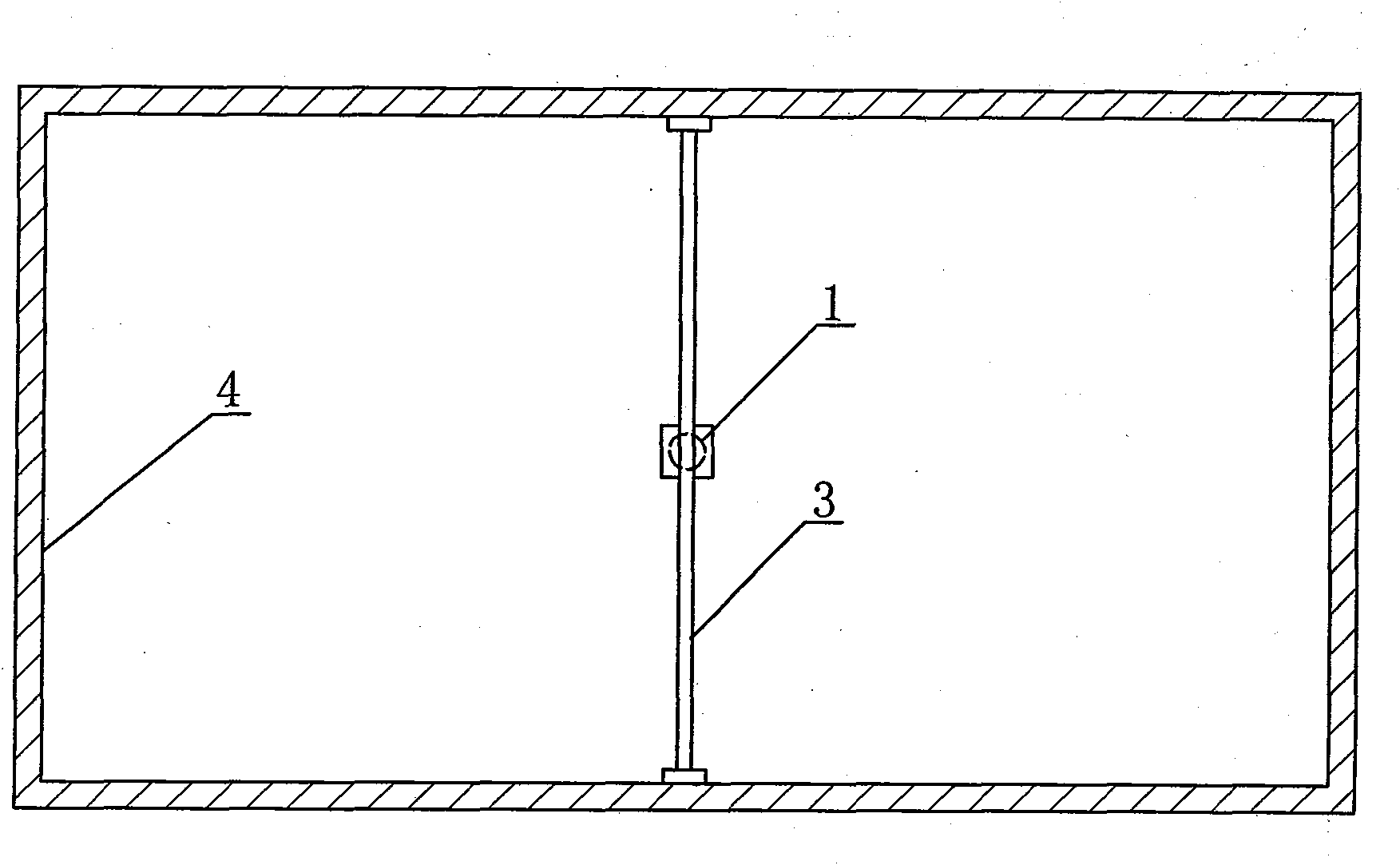
[0031] Such as figure 1 and figure 2 As shown, an LED backlight structure with an inverted light source and a free-form reflector includes a backlight cavity 4 and an LED light source 1. The bottom of the backlight cavity 4 is a free-form reflective surface 2, and the backlight cavity 4 is reflected from the inner wall and the bottom. The free-form reflective surface 2 and the diffusion film 5 placed on the top together form a closed cavity, and the first brightness enhancement film 61, the second brightness enhancement film 62 and the LCD panel are arranged on the diffusion film 5; The LED light source 1 is fixed in the backlight cavity 4 through the light source support frame 3, and is located below the diffuser film 5, the first brightness enhancement film 61, the second brightness enhancement film 62 and the LCD panel and the axis of the free-form reflective surface 2 at the bottom of the backlight cavity 4 above, and the light emitting direction is away from the LCD pan...

Embodiment 2

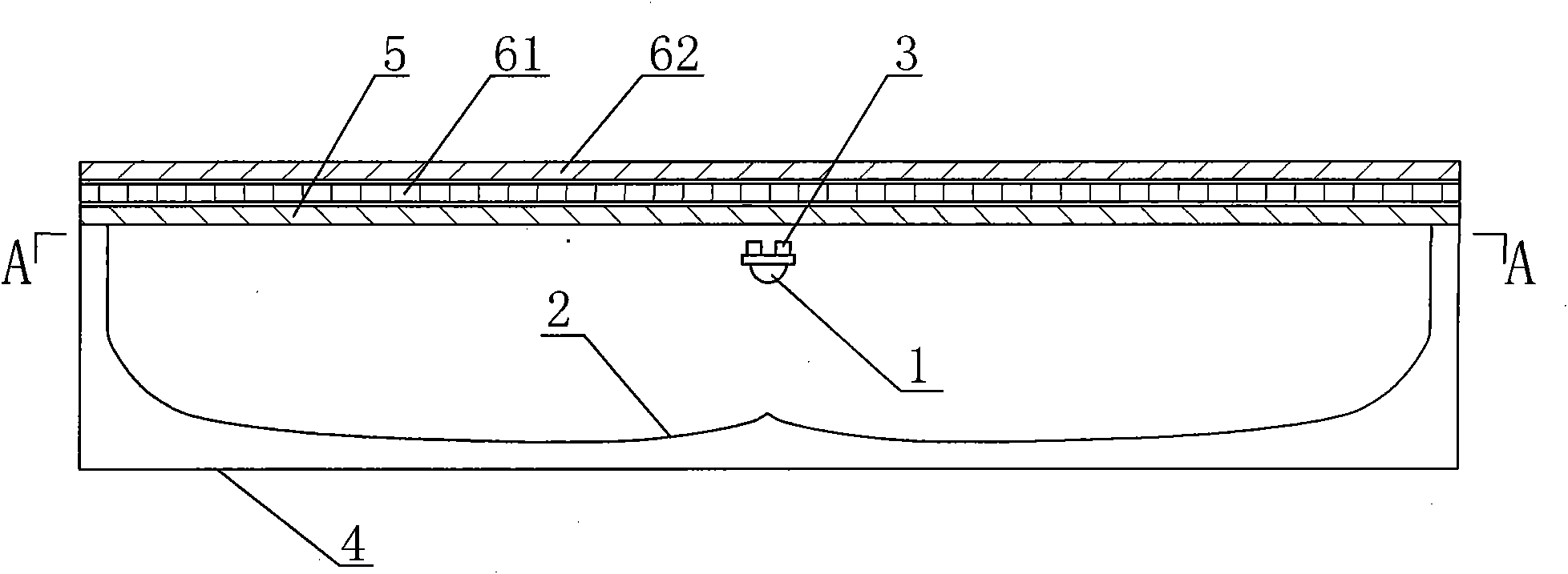
[0036] Such as image 3 , Figure 4 As shown, an LED backlight structure with an inverted light source and a free-form reflector, including a backlight cavity 4, an LED light source 1, a light source support frame 3, a diffusion film 5, a first brightness enhancement film 61 and a second brightness enhancement film 62, The overall structure is similar to that of Embodiment 1, the main difference is that: the light source supporting frame 3 in this embodiment is two metal strips, which are fixedly connected to the backlight cavity 4 .

Embodiment 3

[0038] Such as Figure 5 , Image 6 As shown, an LED backlight structure with an inverted light source and a free-form reflector, including a backlight cavity 4, an LED light source 1, a light source support frame 3, a diffusion film 5, a first brightness enhancement film 61 and a second brightness enhancement film 62, Overall structure is similar to embodiment 1, the main difference is:

[0039] The LED light source 1 of this embodiment is a group of linearly arranged backlight units, each backlight unit is a white LED, and each white LED is respectively fixed on the light source support frame 3, and the light source support frame 3 is two metal bars.


PUM

PropertyMeasurementUnit
reflectanceaaaaaaaaaa

Abstract

The invention relates to an LED backlighting structure provided with a converted light source and using a free-form surface reflector, which comprises a backlighting cavity (4) and an LED light source (1), the bottom of the backlighting cavity (4) is a reflecting surface (2) of a free-form surface, the backlighting cavity (4) is a sealed cavity which is composed of the reflecting inner wall thereof, the reflecting surface (2) of the free-form surface at the bottom and a diffuser film (5) arranged on the top thereof, the diffuser film (5) is provided with a brightness enhance film and other optical films and an LCD panel; the LED light source (1) is fixed in the backlighting cavity (4) through a light source support bracket (3) and is positioned below the diffuser film (5) and right above the axis of the reflecting surface (2) of the free-form surface at the bottom of the backlighting cavity (4), and the emergent direction of light deviates from the LCB panel. The structure has the advantages of large light emergent angle of the light source, small thickness of the whole backlighting system and high whole light effect.

Description

technical field [0001] The invention relates to a backlight system, in particular to an LED backlight structure with an inverted light source and a free-form reflector. technical background [0002] In recent years, with the development of consumer electronic products, the market for flat panel displays has grown larger and larger, wherein liquid crystal displays (Liquid Crystal Display, LCD) account for nearly 90% of the flat panel displays. As a passive light-emitting device, liquid crystal display does not emit light by itself. For transmissive liquid crystal display, it must rely on the backlight source to pass light through the display panel to display graphic images. Cold Cathode Fluorescent Lamp (CCFL) and Light Emitting Diodes (LED) are currently two main technologies of liquid crystal backlight. The main advantages of LED backlights are: good color reproduction, low energy consumption, long life, fast response, better electrical and optical control performance, no ...

Claims


Application Information

Patent Timeline
Patent Type & Authority Applications(China)
IPC IPC(8): F21S8/00F21V7/04F21V5/08F21V13/00F21V19/00G02F1/13357F21Y101/02
Inventor 刘胜刘宗源王恺罗小兵金春晓
Owner GUANGDONG REAL FAITH OPTO
Why Eureka
Try Eureka