Vacuum heat collector

A technology of vacuum heat collection and vacuum cavity, which is applied in the direction of heating devices, thermoelectric devices, and other non-combustion heat generation, and can solve problems such as poor thermal efficiency, insufficient practicability, and inconvenience

Inactive Publication Date: 2010-07-21
骆俊光
View PDF0 Cites 2 Cited by
  • Summary
  • Abstract
  • Description
  • Claims
  • Application Information

AI Technical Summary

Problems solved by technology

[0004] However, during the recovery process of the above-mentioned waste heat, due to the influence of terrain, environment, distance and other factors, the loss of heat energy is quite serious, and the heat transfer effect is better, resulting in a low recovery rate of waste heat, and it can only be applied to close-by It is far away from the place where waste heat is collected, but there are deficiencies such as insufficient practicability and poor thermal effici...

Method used


Image

  • Vacuum heat collector
  • Vacuum heat collector
  • Vacuum heat collector

Examples


Embodiment Construction

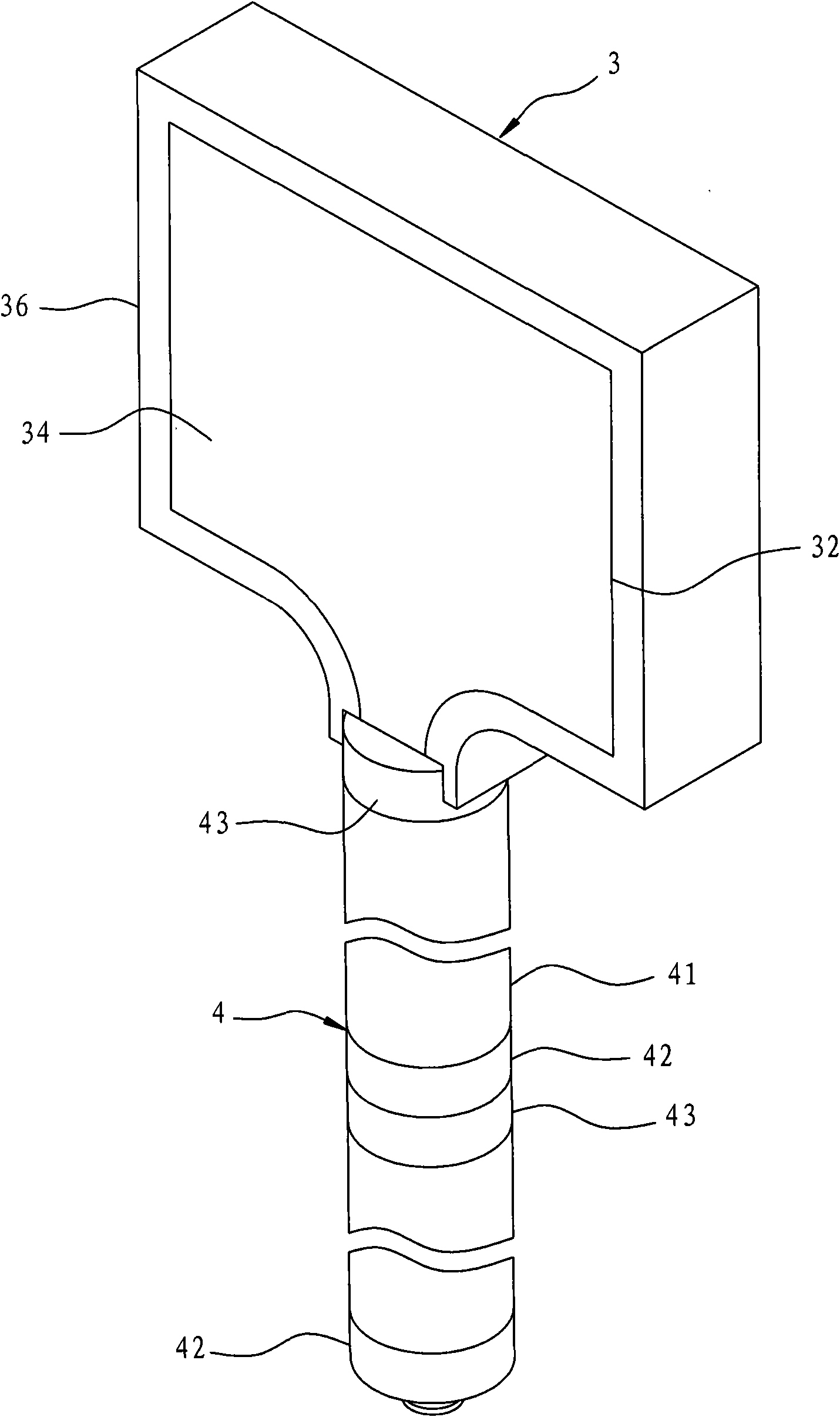
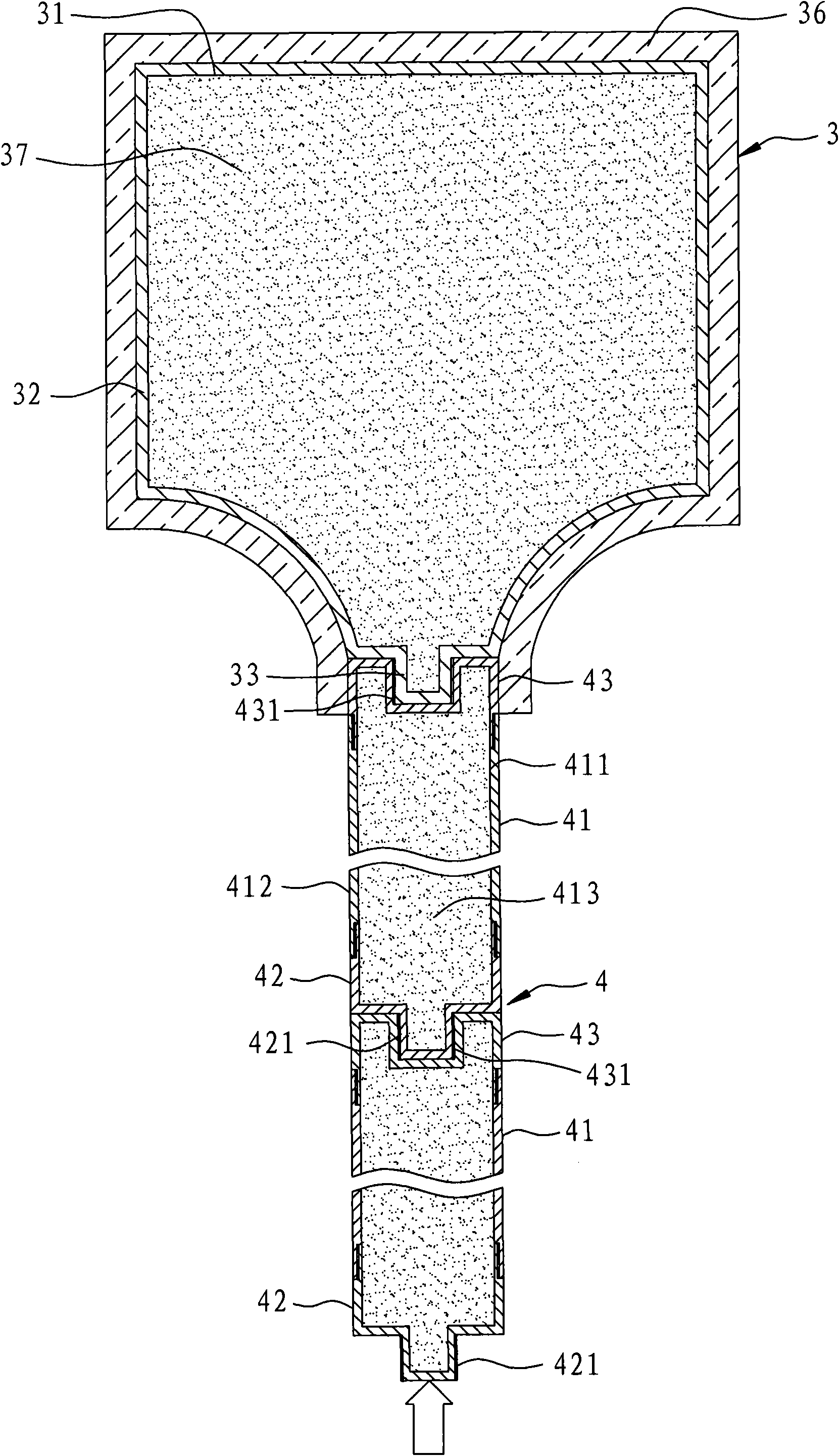
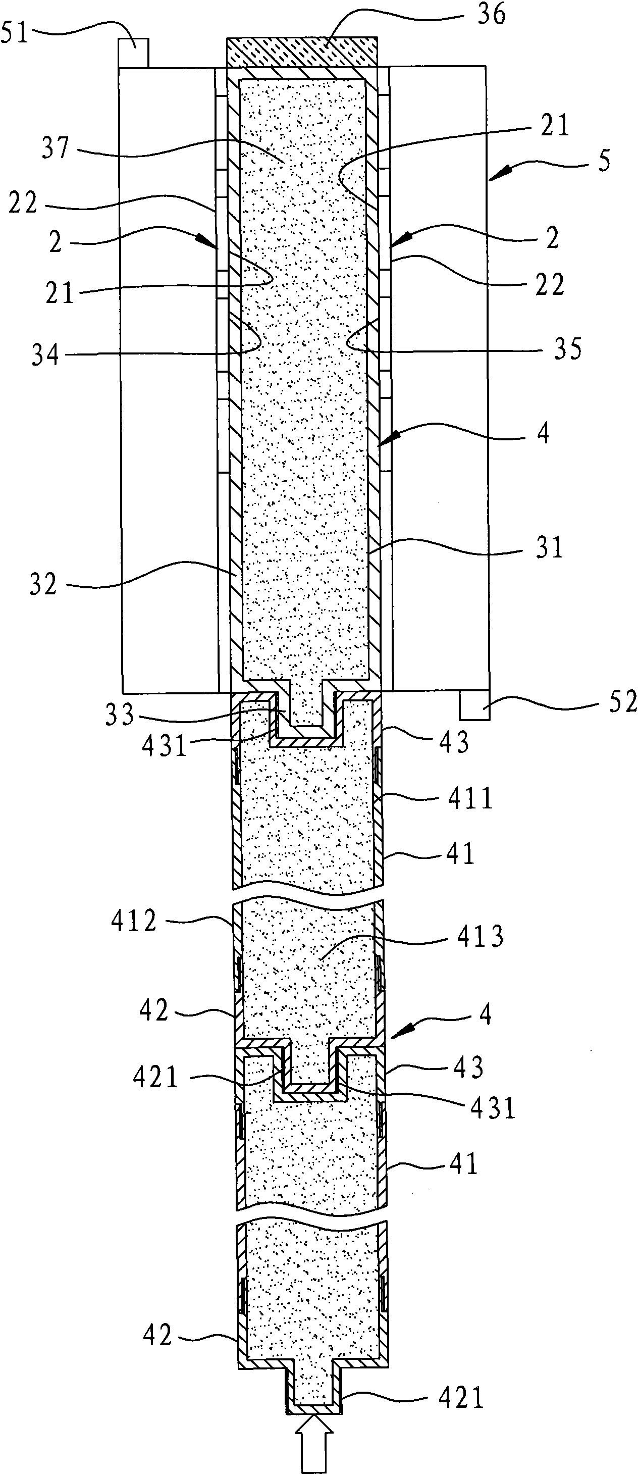
[0022] In order to further explain the technical means and effects of the present invention to achieve the intended purpose of the invention, the specific implementation, structure, characteristics and effects of the vacuum heat collecting device proposed according to the present invention will be described below in conjunction with the accompanying drawings and preferred embodiments. , as detailed below.

[0023] The aforementioned and other technical contents, features and effects of the present invention will be clearly presented in the following detailed description of preferred embodiments with reference to the drawings. Through the description of the specific implementation mode, when the technical means and functions adopted by the present invention to achieve the predetermined purpose can be obtained a deeper and more specific understanding, but the accompanying drawings are only for reference and description, and are not used to explain the present invention be restri...


PUM


Abstract

The invention relates to a vacuum heat collector, which mainly comprises a vacuum cavity and a heat transfer unit, wherein the vacuum cavity comprises a cavity wall and a plurality of temperature conducting particles, the cavity wall defines a chamber, the temperature conducting particles are suspended in the chamber, the temperature conducting particles can generate vibration after being heated, are mutually collided and can release the heat energy, the heat transfer unit comprises at least one temperature superconducting pipe, and the temperature superconducting pipe connects the vacuum cavity and a heat source, and is used for conducting the heat energy generated by the heat source to the vacuum cavity. Thereby, the invention can release the heat energy through the vacuum cavity, and the vacuum cavity can compensate the consumption in the heat energy transfer process, and can effectively improve the heat efficiency, so the invention has high practicability.

Description

technical field [0001] The invention relates to a heat collecting device, in particular to a vacuum heat collecting device which can generate electric energy by using temperature difference. Background technique [0002] In daily life, there are many consumed energy generated but wasted heat energy, such as: water heaters, high-temperature flue gas produced by burners, waste heat emitted by factories, geothermal heat...etc. If the thermal energy can be properly utilized, it will become a renewable energy that meets the needs of environmental protection. [0003] There are many products on the market, such as thermoelectric materials (thermoelectric), heating devices, incubators, boilers, drying devices, etc., which can recover waste heat and convert it into electrical energy or heat energy to achieve resource recovery and energy reuse. Efficacy, but has considerable utility value. [0004] However, during the recovery process of the above-mentioned waste heat, due to the i...

Claims


Application Information

Patent Timeline
IPC IPC(8): F24J3/00H01L35/00
Inventor 骆俊光
Owner 骆俊光
Why Eureka
Try Eureka