Spiral coil heat exchange device

A spiral coil and tubular heat exchange technology, applied in the field of heat exchange devices, can solve the problems of high strength requirements of heat exchange plates, limited pressure bearing capacity, and affecting heat exchange efficiency, etc., and achieve compact structure and pressure bearing capacity High, good sealing effect

Active Publication Date: 2010-07-21
石家庄市石换换热环保有限公司
View PDF11 Cites 10 Cited by
  • Summary
  • Abstract
  • Description
  • Claims
  • Application Information

AI Technical Summary

Problems solved by technology

[0003] ① The strength requirements for the heat exchange plate are high, and the thickness requirements are: general carbon steel plate is 4mm, stainless steel plate is 3mm, the pressure bearing capacity is limited, and because of the weight, the consumables are serious, and the heat exchange efficiency is affected, resulting in energy waste;
[0004] ②When there is a pressure difference in the two channels, the strength of the spiral plate on the side with the lower pressure should also be designed according to the side with the higher pressure. This situation leads to material waste when the pressure difference is too large

Method used


Image

  • Spiral coil heat exchange device
  • Spiral coil heat exchange device
  • Spiral coil heat exchange device

Examples


Embodiment 1

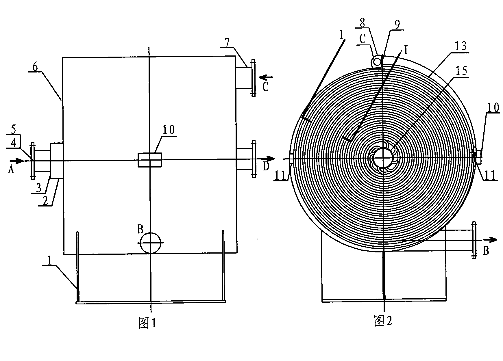
[0033] figure 1 -- Figure 5 Shown is a horizontal spiral coil heat exchanger, metallic.

[0034] The heat exchange device includes a cylinder 6 with a primary medium inlet A and an outlet B, a secondary medium inlet C and an outlet D, such as figure 1 shown. refer to figure 2 , The cylinder body 6 is provided with a central pipe 15 which is a spiral coiled pipe 13 whose axis is spirally involute. The spiral coiled pipe 13 communicates with the central pipe at one end of the axis.

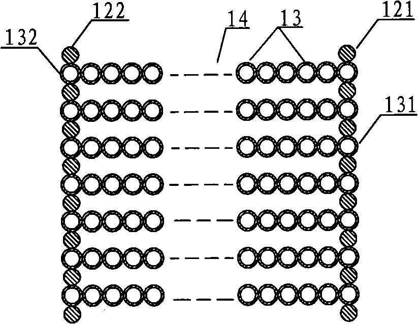
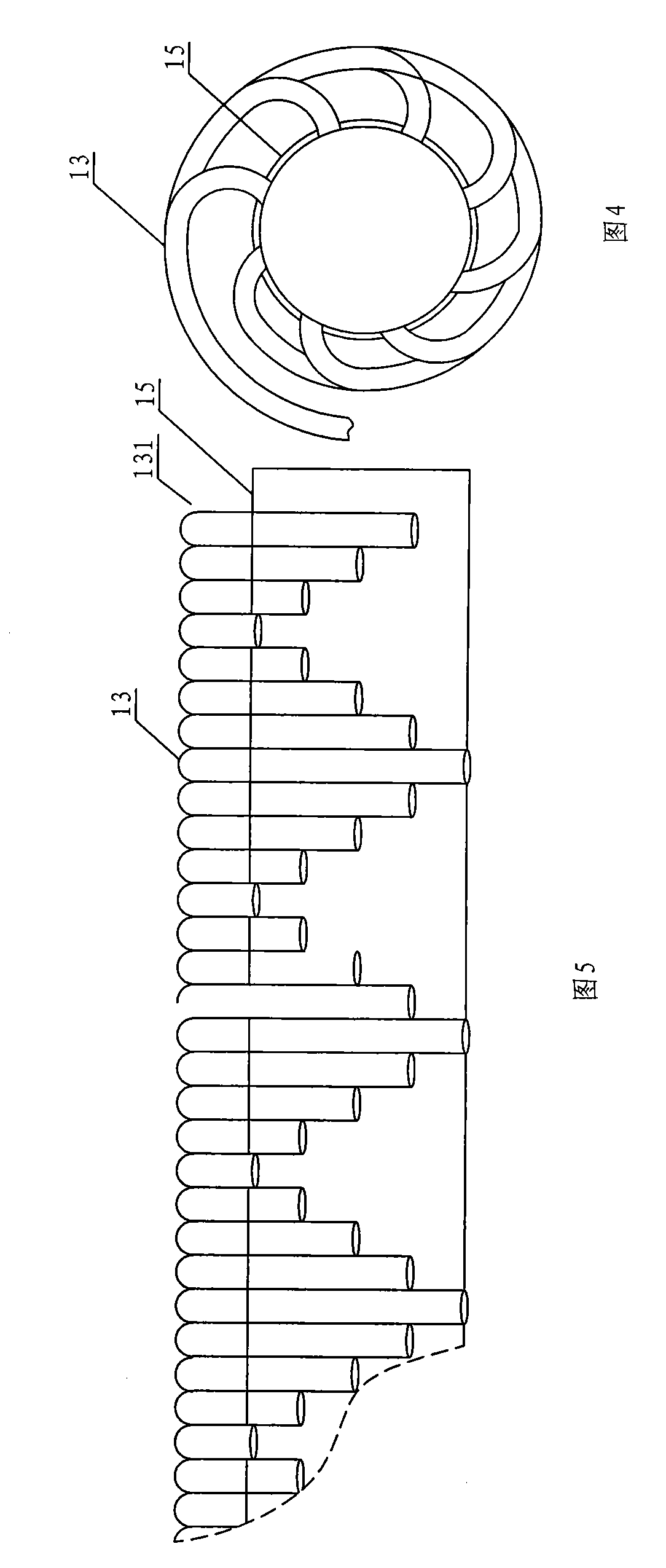
[0035] refer to image 3 , there are many spiral coils 13, and they are arranged side by side without gaps to form a spiral coil group 14, and the spiral coils 13 are mutually staggered on the central tube 15 on the outer wall (refer to figure 2 , Figure 4 , Figure 5 ). Adjacent helical coils 13 are welded and fixed at corresponding helical coils of their helical involutes.

[0036] The two outer end spiral coils 131, 132 located at the edge of the spiral coil group 14 are fixedly weld...

Embodiment 2

[0041] Figure 6 -- Figure 8 Shown is a vertical spiral coil heat exchanger, metal.

[0042] The heat exchange device includes a cylinder body 6 with primary inlet A and outlet B, secondary medium inlet C and outlet D, such as Figure 6 shown. refer to Figure 7 , Figure 8 , The cylindrical body 6 is provided with a central tube 15 and a spiral coil 13 with the central tube 15 as the axis in a spiral involute shape, and the spiral coil 13 communicates with the central tube at one end of the axis.

[0043] refer to Figure 7 , Figure 8 , There are many spiral coil tubes 13, they are arranged side by side without gaps to form a spiral coil tube group 14, and the spiral coil tubes 13 are connected to the central tube 6 on the central partition plate 16 provided in the central tube 15 in a staggered manner. Adjacent helical coils 13 are welded and fixed at corresponding helical coils of their helical involutes.

[0044]The two outer end spiral coils 131, 132 located at ...


PUM


Abstract

The invention discloses a spiral coil heat exchange device, which comprises a barrel with a medium inlet, a medium outlet and a central tube. A plurality of spiral coils are arranged in parallel without clearance in the barrel and are in a spiral involute shape by taking the central tube as the axis. A spiral involute out-tube channel is formed between an outer wall of a spiral coil group and an inner wall of the barrel. A spiral involute in-tube channel is composed of the spiral coil group and the central tube; and two media perform reverse-flow heat exchange in the two independent spiral involute channels respectively. The spiral coil heat exchange device has the advantages of greatly increasing the heat exchange area, improving the heat exchange efficiency and energy utilization degree, reducing the thickness of the tube wall on the premise of not increasing the length of the pipeline, along with compact structure, small volume and light weight, high bearing capacity, good sealing effect and no streaming phenomenon. The spiral coil heat exchange device is applied to energy, petroleum, chemical industry, daily life and other fields, can be used as the heat exchange device for boilers, water heaters, cooling towers and other devices, and can be singly used for performing heat exchange between two fluids of gas and gas, liquid and liquid, and gas and liquid at different temperatures.

Description

technical field [0001] The invention belongs to a device for exchanging heat between media with different temperatures, in particular to a spiral coil heat exchange device. Background technique [0002] Heat exchange devices are used in energy, petroleum, chemical and other industries and in daily life of residents. Existing heat exchange devices include shell-and-tube type, casing type, and spiral plate type. According to the respective flow modes of cold and hot fluids, they can be divided into direct flow, wave flow, swirl flow inside the pipe, flow around the pipe, baffle flow, swirl flow, etc. Among them, the counterflow of hot and cold fluids and their respective swirling flow is an ideal way of heat exchange effect. The spiral plate heat exchanger belongs to this type. For example, the Chinese invention patent ZL992082013 discloses a "spiral plate heat exchanger". It is composed of cold and hot medium inlet and outlet and spirally curled heat exchange plate. In its s...

Claims


Application Information

Patent Timeline
Patent Type & Authority Applications(China)
IPC IPC(8): F28D7/02
CPCF28D7/04Y02P20/10
Inventor 谢建斌霍现霞杨泽林冯青秀张秋宁白健康
Owner 石家庄市石换换热环保有限公司
Why Eureka
Try Eureka