Guided wave signal analyzing method based on time delay

A signal analysis method and time delay technology, applied in the field of non-destructive testing signal analysis, can solve the problems that the original signal cannot distinguish the direction, the multi-channel signal cannot be synthesized into a single analysis signal, etc., to achieve the effect of increasing power, realizing frequency, and broadening the detection frequency band

Active Publication Date: 2010-07-21
BEIJING UNIV OF TECH
View PDF0 Cites 21 Cited by
  • Summary
  • Abstract
  • Description
  • Claims
  • Application Information

AI Technical Summary

Problems solved by technology

[0005] The purpose of the present invention is to solve the current situation that the multi-channel signals collected by the ultrasonic guided wave equipment cannot be synthesized into a single analysis signal, and the direction cannot be distinguished by using the original signal

Method used


Image

  • Guided wave signal analyzing method based on time delay
  • Guided wave signal analyzing method based on time delay
  • Guided wave signal analyzing method based on time delay

Examples


Embodiment Construction

[0041] Provide following test embodiment in conjunction with the content of the inventive method:

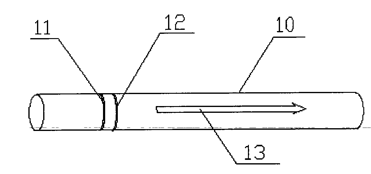
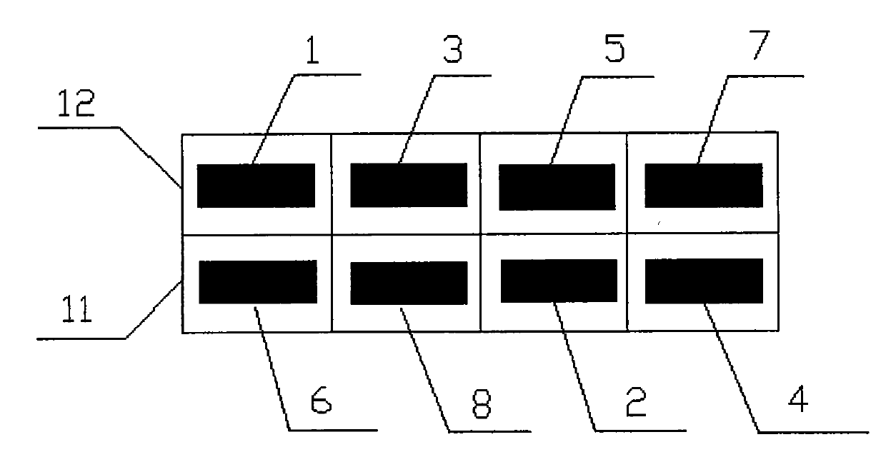
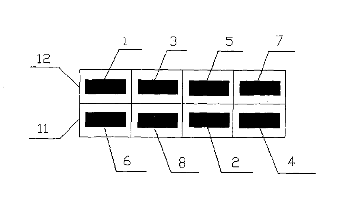
[0042] see figure 1 , figure 2 As shown, 10 is the pipe, 11 is the B ring, 12 is the A ring, 13 is the direction from the B ring to the A ring along the pipe axis; 1-8 is the identification of channel 1 to channel 8.

[0043]Step 1. Install the two sensor rings, A and B, with an interval of 35mm, on the steel transportation pipeline along the circumferential direction. Divide the two sensor rings into four quadrants according to their positions, and the sensors in each quadrant are a sensor group, occupying one signal channel. The larger the pipe diameter, the higher the number of sensors in each quadrant and the more sensors per channel.

[0044] Step 2. Align the 8 channels according to figure 2 The order in the book is numbered 1-8. Then start sending the signal. The transmission is divided into 5 rounds in total, using 8-cycle Hanning window modulated sinusoidal sign...


PUM


Abstract

The invention discloses a guided wave signal analyzing method based on time delay. The time delay and the linear superposition are carried out on the basis of multiple groups of original signals for detecting ultrasonic guided wave, and multiple groups of original signals are separated in directions and combined into two detection result curves finally. The method comprises the steps of: mounting N sensors, wherein each sensor group corresponds to one channel, the sensors are divided into an A-ring and a B-ring and respectively set in odd number and even number, and the interval between the A-ring and the B-ring is 1/4 of the wavelength of exciting signal central frequency; selecting M windowing modulation sine waves with different central frequencies and the certain periodicity as the exciting signals, wherein the M turns of exciting signals have respective central frequency and bandwidth in the frequency domain, each turn of exciting signals covers a certain frequency range, and M*N*N groups of data are obtained by exciting and changing the central frequencies for many times; and obtaining a final pipeline detection curve graph by the calculation to realize the separation in the direction of detection and the separation of symmetrical and unsymmetrical signals, which is convenient to find out defects on the pipeline.

Description

technical field [0001] The invention relates to a guided wave signal analysis method based on time delay, and belongs to the field of nondestructive detection signal analysis. Background technique [0002] Ultrasonic guided wave detection of defects and damages in pipelines is a new pipeline detection technology that has emerged in recent years. Compared with conventional magnetic flux leakage, eddy current, and ray methods, it has the advantages of high detection efficiency, long propagation distance, large detection range, no need to peel off the outer cladding, no need to fully excavate buried pipelines, and online detection. General pipeline detection, for elevated pipelines, clad pipelines, buried pipelines, pipelines passing through road subgrade sections and wall sections, pipelines running in water, etc. Compared with traditional ultrasonic testing, ultrasonic guided wave technology has the advantages of long detection distance (up to 200 meters), 100% detection of ...

Claims


Application Information

Patent Timeline
Patent Type & Authority Applications(China)
IPC IPC(8): G01N29/44
Inventor 吴斌符浩佟文强王维斌郑阳宋国荣周伟何存富
Owner BEIJING UNIV OF TECH
Why Eureka
Try Eureka