Shockproof movement of revolution meter

A tachometer and plastic technology, applied in speed/acceleration/shock measurement, speed/acceleration/electric shock meter details, measuring devices, etc., can solve the problems of unreasonable magnetic ring position, high height, large volume, etc., and achieve reduction Effects of small pointer shaking, changing torsion torque, and enhancing magnetic strength

Inactive Publication Date: 2010-07-21
韩百军
View PDF0 Cites 2 Cited by
  • Summary
  • Abstract
  • Description
  • Claims
  • Application Information

AI Technical Summary

Problems solved by technology

However, the magnet material of the original device is ferrite material with weak magnetic field, so the corresponding hairspring torque is also selected to be small. With such a structure, the pointer is easy to shake under strong vibration; the position of the magnetic ring is unreasonable and The volume is large, so that the height of the entire movement reaches 38mm, which is relatively high

Method used


Image

  • Shockproof movement of revolution meter
  • Shockproof movement of revolution meter
  • Shockproof movement of revolution meter

Examples


Embodiment Construction

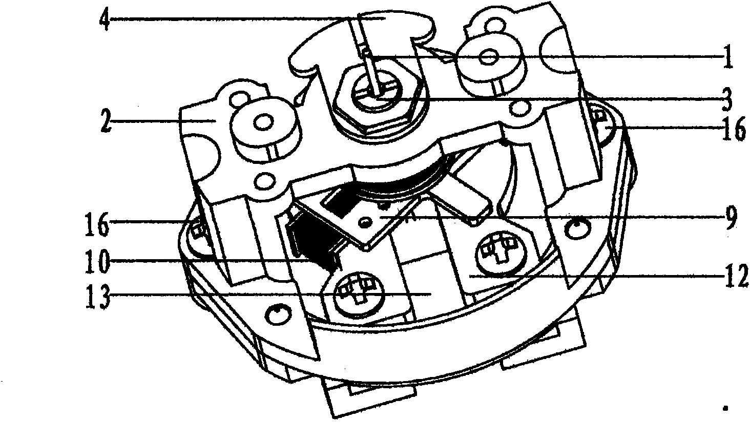
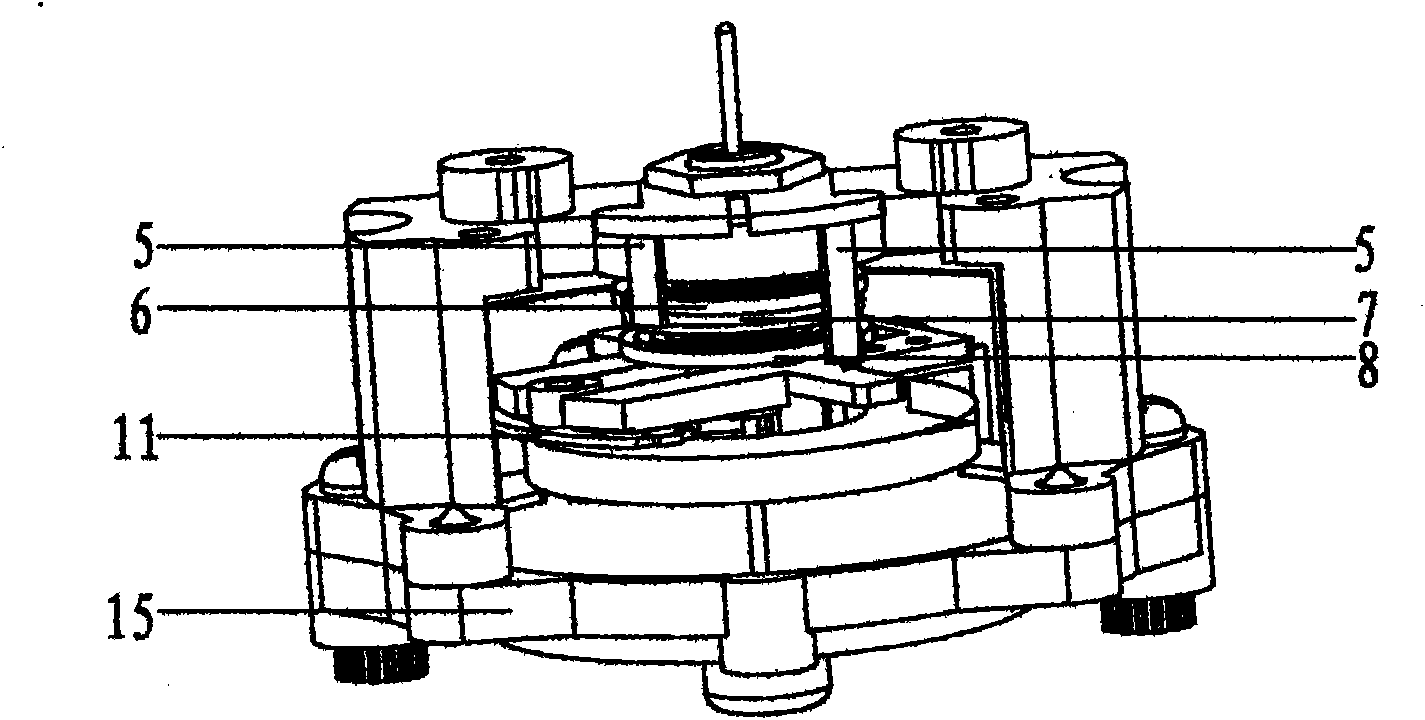
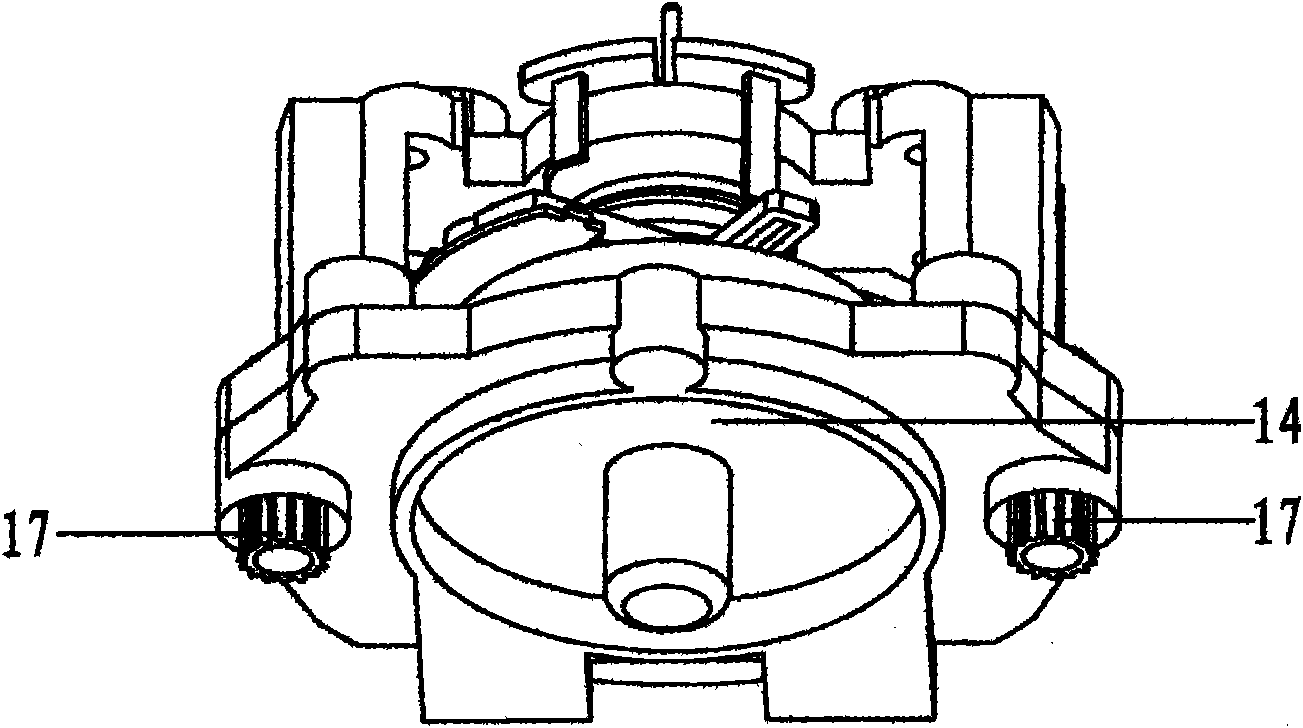
[0011] The pure iron sheet (14), fan-shaped neodymium iron boron magnet (13), Ω type pure iron (12) with output shaft base are adorned successively in the plastic lower housing (15). The output shaft sleeve (3) and the insulating piece (4) for adjusting the tension of the hairspring are installed in the middle of the upper horizontal bar of the plastic upper case (2), fixed with hex nuts (17), and two pieces of fixed hairspring are installed on the insulating piece (4) The small copper sheet of the head is also the electrical signal lead-in point (5). The output shaft (1) is placed in the base, passes through the output shaft sleeve (3), and the protruding part is used for adornment pointer. The output shaft (1) is equipped with a cross-shaped plastic sheet (9), a positive direction hairspring (6), a hairspring spacer (7), a reverse direction hairspring (8), and a cross-shaped plastic sheet (9) is equipped with a coil (10) and Balance weight (11), coil (10) is enclosed within...


PUM


Abstract

The invention relates to a device for pushing a pointer of a revolution meter to deviate. A pure ion plate with an output shaft base, a sector Nd-Fe-B magnet and an Omega-shaped pure iron are sequentially installed inside a plastic lower shell. An output shaft sleeve and an insulation plate for adjusting the tension of a hair spring are installed on the middle part of a crossbar on the upper part of a plastic upper shell, and the insulation plate is provided with two small copper pieces for fixing the head of the hair spring and an electric signal lead-in point. An output shaft is arranged inside the base and passes through the output shaft sleeve, and an extension part of the output shaft is used for holding the pointer. The output shaft is provided with a cross plastic piece, a forward-reverse hair spring and a hair spring spacing piece. The cross plastic piece is provided with a balance block and a coil. The coil is sleeved on the Omega-shaped pure iron. The plastic upper and lower shells are fixed by screws. When a revolution electric signal enters from the electric signal lead-in point, and the hair spring is used for conducting the electricity to the coil, an electromagnetic field is generated, under the mutual effect of the electromagnetic field, the magnetic field of the magnet and the hair spring, the output shaft deflects for a given angle so as to indicate the revolution.

Description

Technical field [0001] The invention relates to a device for pushing the pointer of the tachometer to deflect, which converts the analog electric signal of the speed into the deflection angle of the pointer, so as to achieve the purpose of displaying the speed of the speed. Background technique [0002] Existing devices for pushing the tachometer pointer to deflect include a moving coil magnetoelectric instrument movement, a cross coil magnetoelectric instrument movement, and a stepping motor type. Among them, the existing plastic shell moving coil magnetoelectric tachometer movement has a cheap ferrite magnetic ring placed flat on the bottom of the plastic lower shell. The magnet is divided into S and N poles in the axial direction. There is a pure iron disc on the N pole of the pole, and the bottom S pole leads the magnetic circuit to the Ω-shaped pure iron above through the L-shaped pure iron. The Ω-shaped pure iron is covered with a coil, and the output shaft is connecte...

Claims


Application Information

Patent Timeline
Patent Type & Authority Applications(China)
IPC IPC(8): G01P1/04
Inventor 韩百军
Owner 韩百军
Why Eureka
Try Eureka