Piezoelectric self-generating unit for generating electric charge by utilizing direct piezoelectric effect

A piezoelectric effect and self-generating technology, which is applied to piezoelectric effect/electrostrictive or magnetostrictive motors, electrical components, generators/motors, etc., can solve the problems of limited commercial products

Active Publication Date: 2010-07-21
WUHAN UNIV OF TECH
View PDF0 Cites 5 Cited by
  • Summary
  • Abstract
  • Description
  • Claims
  • Application Information

AI Technical Summary

Problems solved by technology

There are many forms and types of mechanical energy in the environment. Although there are different reports on the development of piezoelectric generators, commercialized produ

Method used


Image

  • Piezoelectric self-generating unit for generating electric charge by utilizing direct piezoelectric effect
  • Piezoelectric self-generating unit for generating electric charge by utilizing direct piezoelectric effect
  • Piezoelectric self-generating unit for generating electric charge by utilizing direct piezoelectric effect

Examples


Embodiment 1

[0028]1) Place the cleaned and dried 2 pieces of piezoelectric ceramic sheets and the metal substrate on the operating platform with the adhesive side facing up. Take a small amount of glue for bonding and apply it on the piezoelectric sheet and the metal conductive material, scrape the glue evenly with a small scraper, and quickly stick the two together while applying pressure evenly. After the bonding is completed, the piezoelectric ceramic element is pressed under the plate and left for 24 hours.

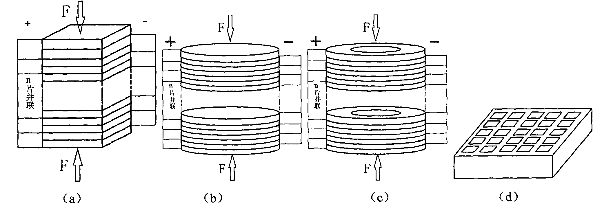
[0029] 2) The piezoelectric ceramic element obtained in step 1 is according to image 3 Solder electrodes as shown.

[0030] 3) The piezoelectric ceramic element obtained in step 2 is potted with epoxy resin, and cured and molded in the range of 60-100°C. That is, a piezoelectric self-generating unit is obtained.

[0031] 4) Connect the piezoelectric self-generating unit to the circuit, and act on the QCZ-2 multi-purpose automatic rutting tester for scientific research, using ...

Embodiment 2

[0033] 1) Place the washed and dried 8 pieces of piezoelectric ceramic sheets and metal substrate on the operating platform with the bonding side facing up. Take a small amount of glue for bonding and apply it on the piezoelectric sheet and the metal conductive material, scrape the glue evenly with a small scraper, and quickly stick the two together while applying pressure evenly. After the bonding is completed, the piezoelectric ceramic element is pressed under the plate and left for 24 hours.

[0034] 2) The piezoelectric ceramic element obtained in step 1 is according to image 3 Solder electrodes as shown.

[0035] 3) The piezoelectric ceramic element obtained in step 2 is potted with epoxy resin, and cured and molded in the range of 60-100°C. That is, a piezoelectric self-generating unit is obtained.

[0036] 4) Connect the piezoelectric self-generating unit to the circuit, and act on the QCZ-2 multi-purpose automatic rutting tester for scientific research, using the f...

Embodiment 3

[0038] 1) Place the cleaned and dried 10 pieces of piezoelectric ceramic sheets and metal substrates on the operating platform with the adhesive side facing up. Take a small amount of glue for bonding and apply it on the piezoelectric sheet and the metal conductive material, scrape the glue evenly with a small scraper, and quickly stick the two together while applying pressure evenly. After the bonding is completed, the piezoelectric ceramic element is pressed under the plate and left for 24 hours.

[0039] 2) The piezoelectric ceramic element obtained in step 1 is according to image 3 Solder electrodes as shown.

[0040] 3) The piezoelectric ceramic element obtained in step 2 is potted with epoxy resin, and cured and molded in the range of 60-100°C. That is, a piezoelectric self-generating unit is obtained.

[0041] 4) Connect the piezoelectric self-generating unit to the circuit, and act on the QCZ-2 multi-purpose automatic rutting tester for scientific research, using t...


PUM


Abstract

The invention discloses a piezoelectric self-generating unit for generating electric charge by utilizing direct piezoelectric effect. Piezoelectric ceramics of which the matrix is PMnS-PZN-PZT system are prepared by the traditional solid-phase method, and bismuth ferrite is doped on the basis; and according to the required quantity of electric charge, piezoelectric ceramic materials with different shapes, sizes and quantities are selected to connect a metal conductive material, and then packaged to form the piezoelectric self-generating unit or the piezoelectric self-generating unit is further combined, is buried in a bituminous concrete pavement structure layer, and is matched with an energy acquisition device, a DC-DC converter, an energy storage device, a power supply monitoring and management system, an illuminating device so as to output the large quantity of electric charge generated by the piezoelectric self-generating unit under the action of mechanical force and supply the electric charge to illumination of high standard highways, tunnels and bridge deck pavement, railways or airport runways, and urban roads and side pavements. The piezoelectric self-generating unit not only can effectively solve the problem that power supply for lamps in urban and rural roads, tunnels and the like is inconvenient, but also is energy-saving, environment-friendly, and safe without high-voltage electric shock danger, and has obvious economic and social value.

Description

technical field [0001] The present invention relates to a piezoelectric self-generating unit that utilizes the positive piezoelectric effect to generate charges. In particular, by laying the piezoelectric self-generating unit under the asphalt concrete road surface or directly using the piezoelectric self-generating unit as a component of the road surface, the vibration or squeezing energy of the vehicle is used to generate electric energy. Background technique [0002] The piezoelectric effect is a phenomenon in which mechanical energy and electrical energy are exchanged in materials. There are two types of piezoelectric effect, direct piezoelectric effect and inverse piezoelectric effect. The positive piezoelectric effect is to convert mechanical energy into electrical energy, that is, when a physical pressure is applied to the piezoelectric material, the electric dipole moment in the material body will be shortened due to compression. At this time, the piezoelectric mate...

Claims


Application Information

Patent Timeline
IPC IPC(8): H02N2/18
Inventor 陈文周静孙华君陈军吴少鹏林伟唐宁朱泉峣
Owner WUHAN UNIV OF TECH
Why Eureka
Try Eureka