Controllable on/off circuit
A technology of switching on and off circuit and resetting circuit, applied in the field of circuits, can solve problems such as cost increase, and achieve the effects of low cost, elimination of hardware jitter and artificial malfunction.
- Summary
- Abstract
- Description
- Claims
- Application Information
AI Technical Summary
Problems solved by technology
Method used
Image

Examples
Embodiment Construction
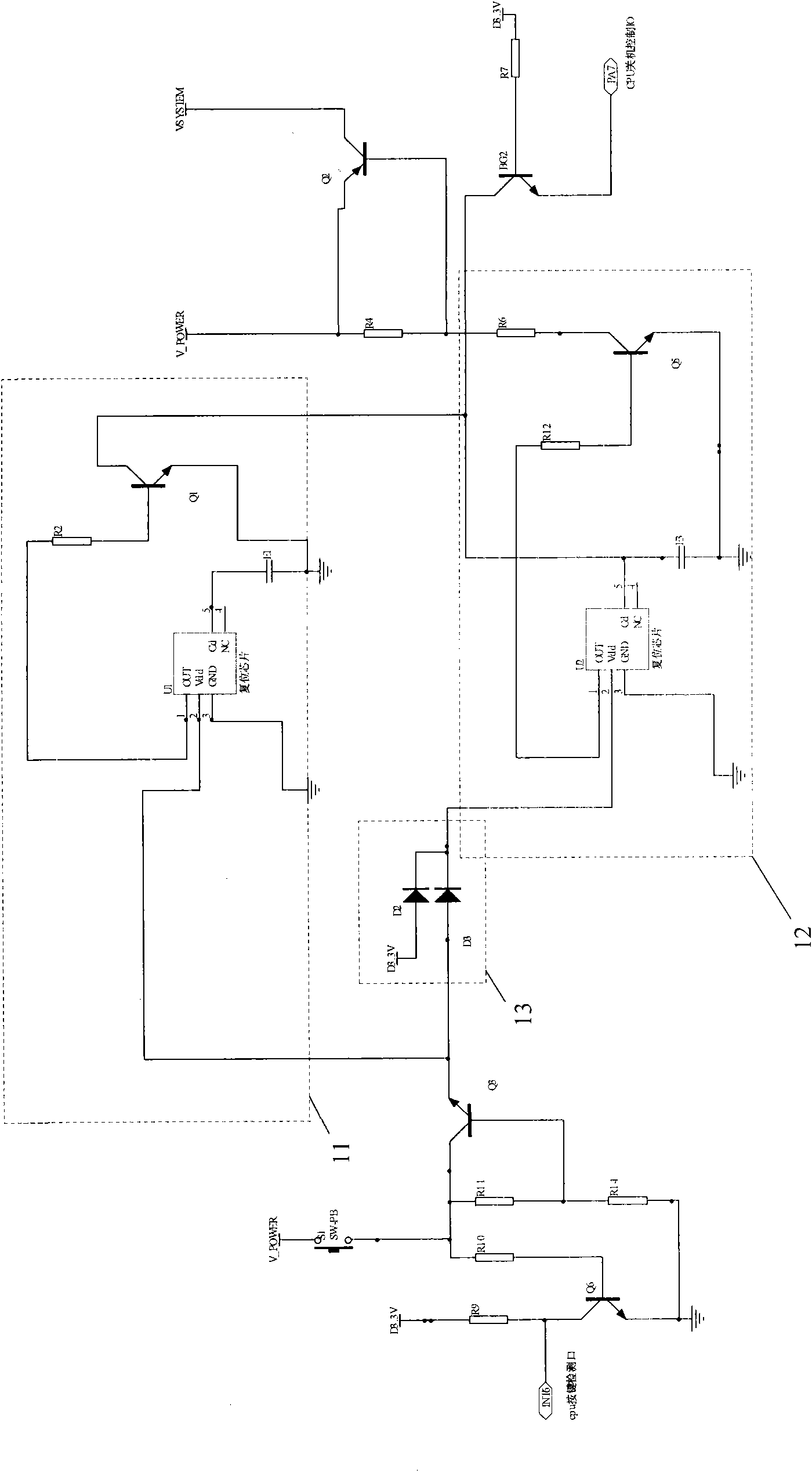
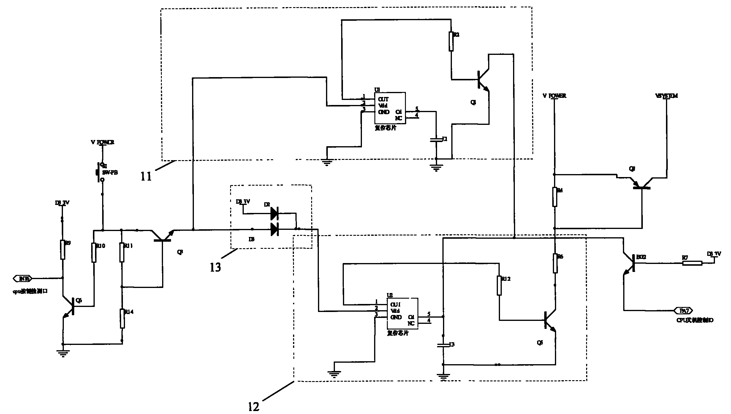
[0017] see figure 2 As shown, a preferred embodiment of the present invention is provided. The controllable switch circuit in this embodiment includes a first reset circuit 11 , a second reset circuit 12 , and a self-locking circuit 13 .
[0018] The first reset circuit 11 further includes a reset chip U1, an adjusting capacitor E1, and an NPN transistor Q1; the second reset circuit 12 further includes a reset chip U2, an adjusting capacitor E3, and an NPN transistor Q5; The reset chips U1 and U2 are both R3112N241A chips, and the capacitance integral durations of E1 and E3 are different; the self-locking circuit 13 adopts a line-or circuit formed by connecting two diodes D2 and D3, and the positive pole of D2 in the self-locking circuit Connect a D3.3V power supply, the positive pole of D3 is connected to the power button S1, and the negative poles of D2 and D3 are connected to the Vdd terminal of the reset chip U2.
[0019] The Vdd end of the reset chip U1 is the input end...
PUM
 Abstract
Description
Claims
Application Information