Rotary transducer with monitoring of the bearing wear and method therefor

An automatic synchronization and transmitter technology, which is applied to bearings, bearing assembly, bearing components, etc., can solve the problem of not being able to reliably and accurately predict the mechanical failure of the detector, and achieve the effect of low design cost.

Active Publication Date: 2010-07-21
堡盟德国有限两合公司
View PDF6 Cites 16 Cited by
  • Summary
  • Abstract
  • Description
  • Claims
  • Application Information

AI Technical Summary

Problems solved by technology

[0010] the downside is that none of these known solutions can reliably and accurately predict mechanical failure of the probe

Method used


Image

  • Rotary transducer with monitoring of the bearing wear and method therefor
  • Rotary transducer with monitoring of the bearing wear and method therefor
  • Rotary transducer with monitoring of the bearing wear and method therefor

Examples


Embodiment Construction

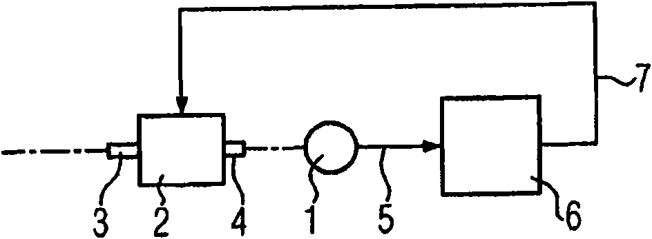
[0046] exist figure 1 A typical use of the automatic synchronization transmitter 1 is shown in . Actuator 2, such as electric motor utilizes its drive shaft 3 to drive the working machine (in figure 1 not shown). The drive machine can, for example, be built in a paper machine and run continuously at 1500 rpm and thus produce 0.78×10 9 turn / year.

[0047] The automatic synchronizing transmitter 1 is connected to the drive shaft 3, or as in figure 1 Shown in is connected to a second drive shaft 4, which is generally rotationally fixedly connected to the first drive shaft 3.

[0048] Automatic synchronization transmitter 1 converts the angular position and / or angular velocity of drive shaft 3 or 4 into electrical signals and feeds these values ​​via line 5 to controller 6 . The regulator 6 derives a control signal from the measurement signal, which is used via a line 7 to control the actuator 2 in order to maintain a predetermined desired value. In the case of a paper machi...


PUM


Abstract

The invention relates to a rotary transducer (1) and to a method for monitoring wear on the latter. The rotary transducer has a detector device (11) having at least one measurement sensor (12). During operation, the measurement sensor can be used to generate a measurement signal (13) which is representative of the angular position and / or velocity of an object which can be connected to the rotary transducer. The detector device (11) has at least one rotary bearing (15) and at least one material measure (16) which can be rotated, by means of the rotary bearing, relative to the measurement sensor and is arranged in the measurement field (17) of the latter. A monitoring device (20) which is connected to the measurement sensor such that data are transmitted and can be used, during operation, to output a state signal (23), which is representative of the state of wear of the rotary transducer, on the basis of the measurement signal is also integrated in the rotary transducer (1). In order tobe able to warn of mechanical failure of the rotary transducer in good time, the monitoring device (20) is provided, according to the invention, with a register (25) which can permanently store a value which is representative of the state of wear of the rotary bearing and is formed from the information relating to the angular position and / or velocity which is contained in the measurement signal.

Description

technical field [0001] The invention relates to an automatic synchronization transmitter, in which a detection device and a monitoring device are integrated, the detection device has at least one measuring sensor, by means of which during operation an angular position and / or representative of an object connected to the automatic synchronization transmitter can be generated For the measurement signal of the angular velocity, the detection device also has at least one rotary bearing and at least one metering device which is rotatably arranged in its measuring field via the rotary bearing relative to the measuring sensor, and the monitoring device is connected to the measuring sensor for data transmission. The invention also relates to a method for monitoring the wear of an automatic synchrotron, which during operation acquires an angular position and / or an angular velocity of a rotating body connected to the automatic synchrotron and emits it as a measurement signal. Background...

Claims


Application Information

Patent Timeline
Patent Type & Authority Applications(China)
IPC IPC(8): F16C19/52G01D3/08
CPCG01D3/08F16C19/52G01M13/04G01P21/02G01P3/481F16C19/525F16C41/007F16C2233/00
Inventor 路塔尔·威尔赫尔梅伯恩哈德·希勒约亨·威尔赫尔梅
Owner 堡盟德国有限两合公司
Why Eureka
Try Eureka