
Liquid tank container

A container and liquid tank technology, applied in the field of large rigid equipment, can solve the problems of unfavorable tank body maintenance, falling off, cracking at the welding seam of the tank body, etc. Effect

Inactive Publication Date: 2010-07-28
SHENGSHI CONTAINER MANAGEMENT SHANGHAI
View PDF0 Cites 12 Cited by
  • Summary
  • Abstract
  • Description
  • Claims
  • Application Information

AI Technical Summary

Problems solved by technology

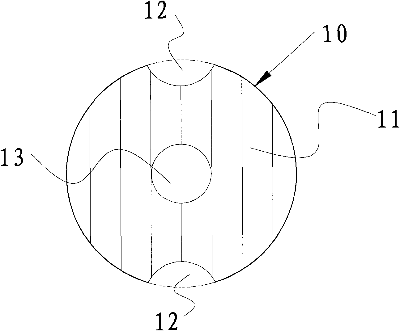
like figure 1 As shown, it is a commonly used anti-wave plate 11 currently installed in the tank to slow down the liquid surge. The anti-wave plate 11 is an integral structure with liquid flow holes 12 on the top and bottom, and a large liquid flow hole 13 in the middle. , the anti-wave plate 11 is directly welded on the inner wall of the tank body 10. This integral anti-wave plate setting has the problem of difficult welding and assembly for some large tank bodies. At the same time, this setting makes the passage of personnel in the tank body It is relatively difficult, and it is not conducive to performing operations such as maintenance of the inside of the tank body during use. Moreover, because the wave-proof plate 11 is directly welded to the inner wall of the tank, the stress at the weld is relatively concentrated. During long-term use, it is constantly being subjected to After the large impact force of the liquid, it is easy to cause damage to the anti-wave plate or fall off from the tank body, and even cause unfavorable conditions such as cracking at the welding seam of the tank body

Method used


Image

  • Liquid tank container
  • Liquid tank container
  • Liquid tank container

Examples


Embodiment Construction

[0038] Below in conjunction with accompanying drawing and specific embodiment the present invention will be described in further detail:

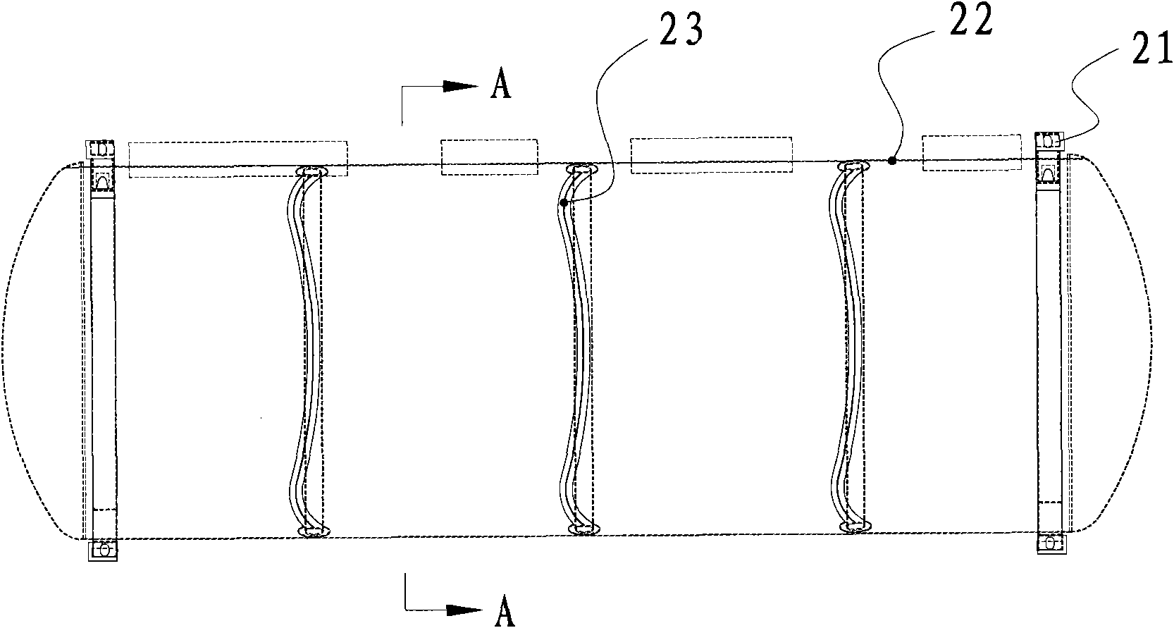
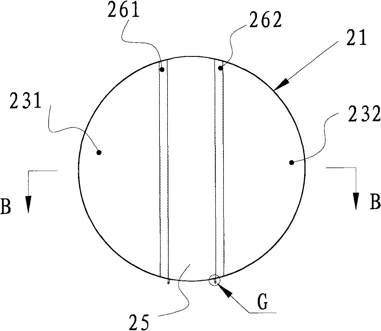
[0039] Such as figure 2 A liquid tank container is shown, which includes a rigid frame body 21 and a tank body 22 welded to the rigid frame body 21 and arranged inside the frame body 21 . The tank body 22 is provided with a wave-proof plate 23 welded along the horizontal direction of the tank body, combined with image 3 , Figure 4 , Figure 5 as well as Figure 6 As shown, the anti-wave plate 23 is composed of a left unit anti-wave plate 231 and a right unit anti-wave plate 232 with an arc-shaped cross section and left and right symmetrical arrangements. A channel 25 is formed between the left unit anti-wave plate 231 and the right unit anti-wave plate 232. One person can be allowed to walk through, on the one hand, it is convenient for maintenance personnel to pass through, and at the same time, the bottom of the tank is in a connec...


PUM


Abstract

The invention discloses a liquid tank container, comprising a framework body and a tank body which is fixedly connected with the framework body, wherein at least one group of breakwaters are laterally and fixedly arranged in the tank body along the tank body and comprise at least two breakwater units, a gap between at least two unit breakwaters can at least allow one person to pass through, and the bottom of the tank body is communicated at least. Compared with the prior art, the liquid tank container has simple and reliable structure, easy processing and manufacturing and convenient maintenance in the tank body by the maintenance personnel.

Description

technical field [0001] The invention relates to a large rigid equipment for liquid storage or transportation, in particular to a liquid tank container. Background technique [0002] At present, known containers for transporting liquids, such as liquid tank containers, municipal greening sprinklers, sprinklers, marine water tanks, oil tanks, oil tankers or other containers for transporting liquids, during transportation, with acceleration, deceleration, turning and up and down In the case of bumps and other conditions, the liquid in the tank will surge, and the excessive impact force generated by the liquid surge will damage the tank and affect the driving of the transport vehicle loaded with the tank. The conventional method to solve this problem is to install a Breakout panels to slow down liquid surges. Such as figure 1 As shown, it is a commonly used anti-wave plate 11 currently installed in the tank to slow down the liquid surge. The anti-wave plate 11 is an integral s...

Claims


Application Information

Patent Timeline
Patent Type & Authority Applications(China)
IPC IPC(8): B65D90/52B65D90/02B65D90/50
Inventor 健·万·奥普斯特
Owner SHENGSHI CONTAINER MANAGEMENT SHANGHAI
Learn More