
Oil sealing device on end part of steam turbine shaft

A steam turbine and shaft end technology, applied in the direction of engine seals, mechanical equipment, engine components, etc., can solve problems such as the influence of the safe and stable operation of the coupling, the oil seal at both ends of the steam turbine shaft cannot meet the needs of the market, etc., to prevent Oil leakage, easy installation, enhanced sealing effect

Active Publication Date: 2010-07-28
HANGZHOU STEAM TURBINE
View PDF7 Cites 2 Cited by
  • Summary
  • Abstract
  • Description
  • Claims
  • Application Information

AI Technical Summary

Problems solved by technology

Although such a structural design can meet the requirements of production and operation in terms of oil sealing, due to the existence of the shield and the direct contact of the coupling with the leaked oil during sealing, it has brought certain problems to the safe and stable operation of the coupling. Impact
[0003] Moreover, since the coupling is a key connecting part, it is particularly important in the supporting operation. The standards for the coupling of each steam turbine manufacturer are also different. However, with the development and development of the market, changes in supporting manufacturers, and user requirements, steam turbine shaft The design of oil seals at both ends can no longer meet the needs of the market. For example, ATLAS resolutely does not use the form of the shield to cover the coupling to achieve oil seal.
[0004] In order to better adapt to the development of the steam turbine industry, the end of the steam turbine shaft should be made fully enclosed, but the existing oil sealing device cannot meet this demand

Method used


Image

  • Oil sealing device on end part of steam turbine shaft
  • Oil sealing device on end part of steam turbine shaft
  • Oil sealing device on end part of steam turbine shaft

Examples


Embodiment 1

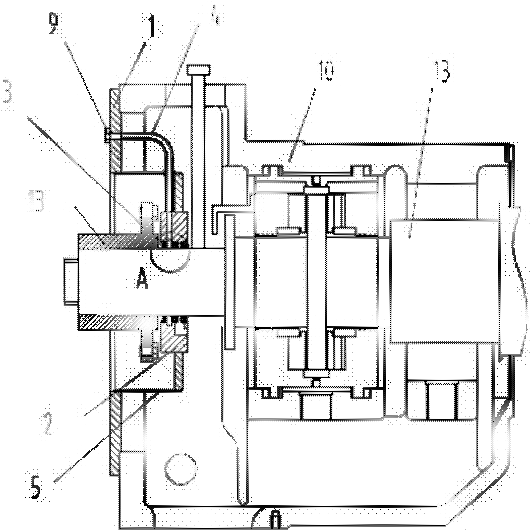
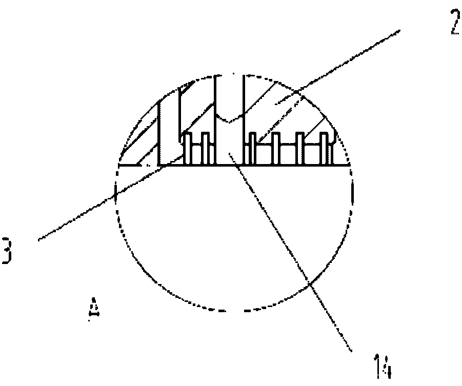
[0017] Such as figure 1 As shown, the oil sealing device at the end of the steam turbine shaft described in this embodiment is used to seal the front end of the steam turbine shaft. The oil sealing device mainly includes a sealing ring, which is mainly fixedly arranged on the front support of the steam turbine. The outer seal ring 1 on the seat 10 and the inner seal ring 2 sleeved on the steam turbine shaft 12 are composed of the outer seal ring 1 and the inner seal ring 2 which are distributed in a stepped manner and are connected by a seal plate 5 between them. The inner seal ring 2 The ring mouth is provided with sealing teeth 3, so that the sealing ring can be accurately inserted into the end of the steam turbine shaft 12 and the steam turbine front support 10 after the coupling 13 is installed, the sealing ring is formed by connecting the upper and lower parts, and The connecting surface is the middle parting surface of the sealing ring, and the upper and lower parts are co...

Embodiment 2

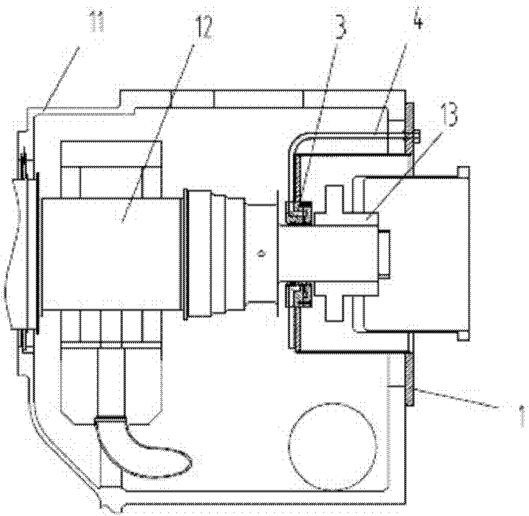
[0020] Such as figure 2 As shown, the oil sealing device at the end of the steam turbine shaft described in this embodiment is used to oil seal the rear end of the steam turbine shaft. The oil sealing device mainly includes a sealing ring, which is mainly fixedly arranged behind the steam turbine The outer sealing ring 1 on the support 11 and the inner sealing ring 2 sleeved on the steam turbine shaft 12 are composed of the outer sealing ring 1 and the inner sealing ring 2 which are distributed in a stepped manner and are connected by a sealing plate 5 between them. The inner sealing ring 2 The inner ring port is provided with sealing teeth 3, and the distance between the sealing teeth 3 and the turbine shaft 12 is selected in the range of 0-0.015μm, here is 0.010μm; in order to make the sealing ring accurate after the coupling 13 is installed Install the turbine shaft 12 and the end of the turbine support without error. The sealing ring is formed by connecting the upper and lo...


PUM


Abstract

The invention discloses an oil sealing device on end part of a steam turbine shaft. The oil sealing device mainly comprises a sealing ring. The oil sealing device is characterized in that: the sealing ring mainly comprises an outer sealing ring and an inner sealing ring, and an inflation tube, wherein the outer sealing ring is fixedly arranged on a steam turbine support; the inner sealing ring is sleeved on the steam turbine shaft; the outer sealing ring and the inner sealing ring are distributed in a stepped mode and the outer sealing ring is connected with the inner sealing ring through a sealing plate; the inner ring port of the inner sealing ring is provided with sealing teeth; the air inlet of the inflation tube is arranged on the ring surface of the outer sealing ring, and the air outlet of the inflation tube is arranged in a clearance between the sealing teeth on the inner sealing ring; and the sealing ring is also provided with a mounting hole and a positioning hole. In the oil sealing device on the end part of the steam turbine shaft, the special outer sealing ring and the special inner sealing ring are distributed in a stepped mode, so a shaft coupling is open and exposed outwards; and the outer sealing ring and the inner sealing ring are in good fit with the steam turbine support and the steam turbine shaft well respectively, so full enclosed state of oil at the two ends of the steam turbine shaft and excellent sealing effect are achieved.

Description

Technical field [0001] The invention relates to a sealing device applied to a steam turbine, in particular to an oil sealing device at the end of a steam turbine shaft. Background technique [0002] Both ends of the current design of the steam turbine shaft are open, without any oil sealing measures. The oil seal at both ends of the steam turbine shaft is completed by the coupling and the shield. The shield covers the coupling and works with the coupling. Achieve a good sealing effect. Although such a structural design can meet the requirements of production and operation on the oil seal, the existence of the shield and the direct contact of the coupling with the leaking oil during the seal bring a certain degree to the safety and stability of the coupling. Impact. [0003] Moreover, because the coupling is a key connecting component, it is particularly important in supporting operations. The standards for couplings of various steam turbine manufacturers are different. However, w...

Claims


Application Information

Patent Timeline
IPC IPC(8): F01D11/00F16J15/40
Inventor 郭晴蓉傅培恒
Owner HANGZHOU STEAM TURBINE
Learn More