Circularly moving piston internal combustion engine

A circular motion, internal combustion engine technology, used in the field of internal combustion engines, natural gas engines, and gasoline engines, can solve the problems of energy consumption of compressed mixed gas, small piston power stroke, and waste of work power, so as to reduce energy consumption, increase power stroke, and improve The effect of efficiency

Active Publication Date: 2013-04-17
西安丁杰动力科技有限公司
View PDF0 Cites 0 Cited by
  • Summary
  • Abstract
  • Description
  • Claims
  • Application Information

AI Technical Summary

Problems solved by technology

[0002] In the prior art, comparatively mature piston reciprocating internal combustion engines and rotor internal combustion engines are generally used, and its existing engines have congenital defects: 1. The piston of the existing piston linear motion internal combustion engine is a linear reciprocating motion up and down, and the piston The working stroke is small, and the energy generated by the expansion gas is discharged without full (work) utilization, resulting in waste
In the process of converting the chemical energy of the fuel into mechanical energy in the piston up and down linear reciprocating internal combustion engine, the energy is wasted needlessly due to the compression of the gas.
2. The work of existing rotor-type internal combustion engines is to push the rotor to do directional rotation by the directional combined external force produced by the end of the combustion chamber with relatively large volume and relatively strong force overcoming the end of the combustion chamber with relatively small volume and relatively weak force, or in other words: Output work = big end work - small end work, this kind of structure that consumes part of the work to push the rotor to rotate causes waste of work energy
Its disadvantages are complex structure, energy consumption of compressed mixed gas, low work efficiency, etc.

Method used


Image

  • Circularly moving piston internal combustion engine
  • Circularly moving piston internal combustion engine
  • Circularly moving piston internal combustion engine

Examples


Embodiment Construction

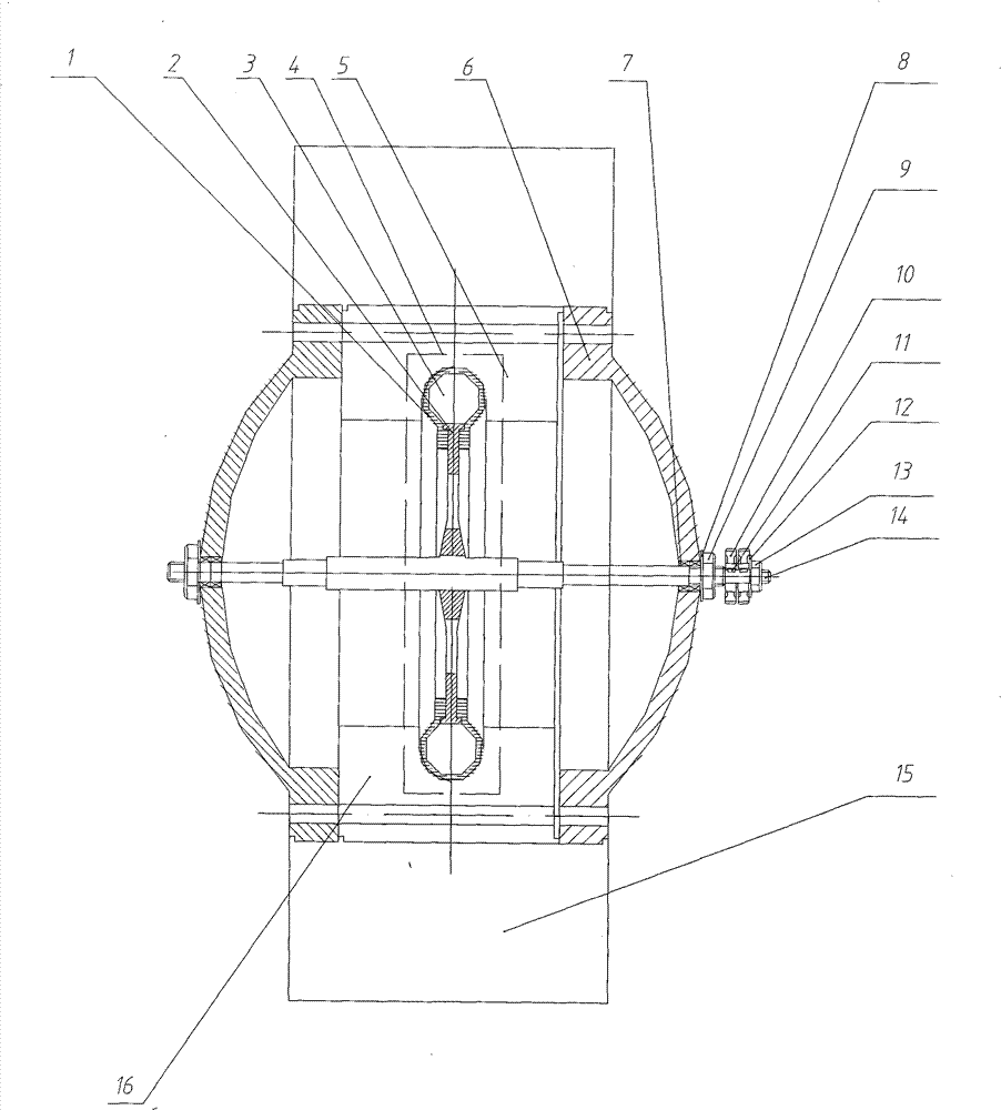
[0021] see figure 1 , the cylinder mechanism is composed of a fixed piston cylinder mechanism 4 and a timing gear 10 on the central shaft 14 on the housing, wherein the piston cylinder mechanism 4 is composed of a circular faceplate 2 with a cylindrical piston 3 and a C-shaped ring Shaped cylinder 1 is formed, and housing is formed by the connection of cylinder outer casing 5 and internal combustion engine casing 6. In the housing, the central axis 14 is connected and positioned through the bearing 7, the spring pad 8 and the fixing bolt 9, and the circular faceplate 2 with the cylindrical piston 3 is fixed in the middle of the central axis 14, and the cylindrical piston 3 is fixed on the outer circumference of the circular faceplate 2 evenly. Distribution, at least two or more. The central shaft 14 is not only the center of the circular motion of the piston of the piston rotary internal combustion engine, but also the power output shaft of the internal combustion engine. Be...


PUM


Abstract

The invention relates to an internal combustion engine, a gasoline engine and a natural gas engine, in particular to a circularly moving piston internal combustion engine. In the prior art, linearly moving piston internal combustion engines have defects of small working stroke of pistons and energy waste, and the current rotator internal combustion engines consume part of power to push rotationalmoving structures of rotators, which causes energy waste. The invention aims to provide the circularly moving piston internal combustion engine comprising a cylinder mechanism and a cam mechanism. The cylinder mechanism comprises a piston cylinder mechanism and a timing gear both fixed on a central shaft which is arranged on a shell, the shell is formed through connecting an outer cylinder sleeveand an outer shell of the internal combustion engine; and the cam mechanism comprises a timing gear member and a camshaft member. The circularly moving piston internal combustion engine changes the linear motion of pistons into the curvilinear motion of pistons in current linearly moving piston internal combustion engines, thereby increasing the working stroke, increasing the work doing efficiency, eliminating the energy waste, and thoroughly solving problems in the prior art.

Description

1. Technical field [0001] The invention relates to an internal combustion engine, a gasoline engine and a natural gas engine, in particular to a piston circular motion internal combustion engine. 2. Technical background [0002] In the prior art, comparatively mature piston reciprocating internal combustion engines and rotor internal combustion engines are generally used, and its existing engines have congenital defects: 1. The piston of the existing piston linear motion internal combustion engine is a linear reciprocating motion up and down, and the piston The working stroke of the air compressor is small, and the energy generated by the expansion gas is discharged without full (work) utilization, resulting in waste. Simultaneously, the connecting rod and the crank of the piston up and down linear reciprocating internal combustion engine do not transmit the thrust generated by the expansion gas to the piston, so that the thrust is accurately and completely transmitted, whic...

Claims


Application Information

Patent Timeline
Patent Type & Authority Patents(China)
IPC IPC(8): F02B53/02F02B53/04F02B53/12
CPCY02T10/17Y02T10/12
Inventor 丁杰丁超然
Owner 西安丁杰动力科技有限公司
Why Eureka
Try Eureka