
Cam mechanism inside internal combustion engine with piston doing circular motion
A cam mechanism and circular motion technology, applied in the fields of internal combustion engines, gasoline engines, and natural gas engines, can solve the problems of energy consumption of compressed mixed gas, small piston working stroke, and waste of working energy, so as to reduce energy consumption, increase working stroke, The effect of improving efficiency
Patent Information
- Authority / Receiving Office
- CN · China
- Patent Type
- Patents(China)
- Current Assignee / Owner
- Publication Date
- 2013-11-06
Smart Images
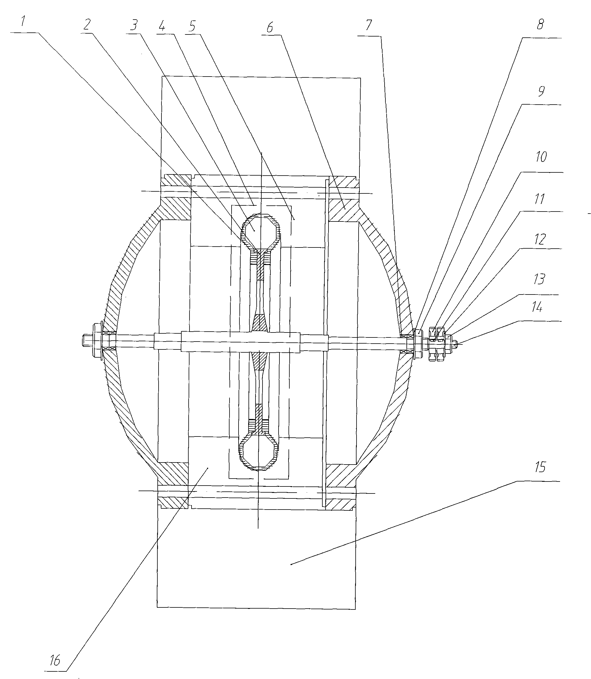
Figure 1 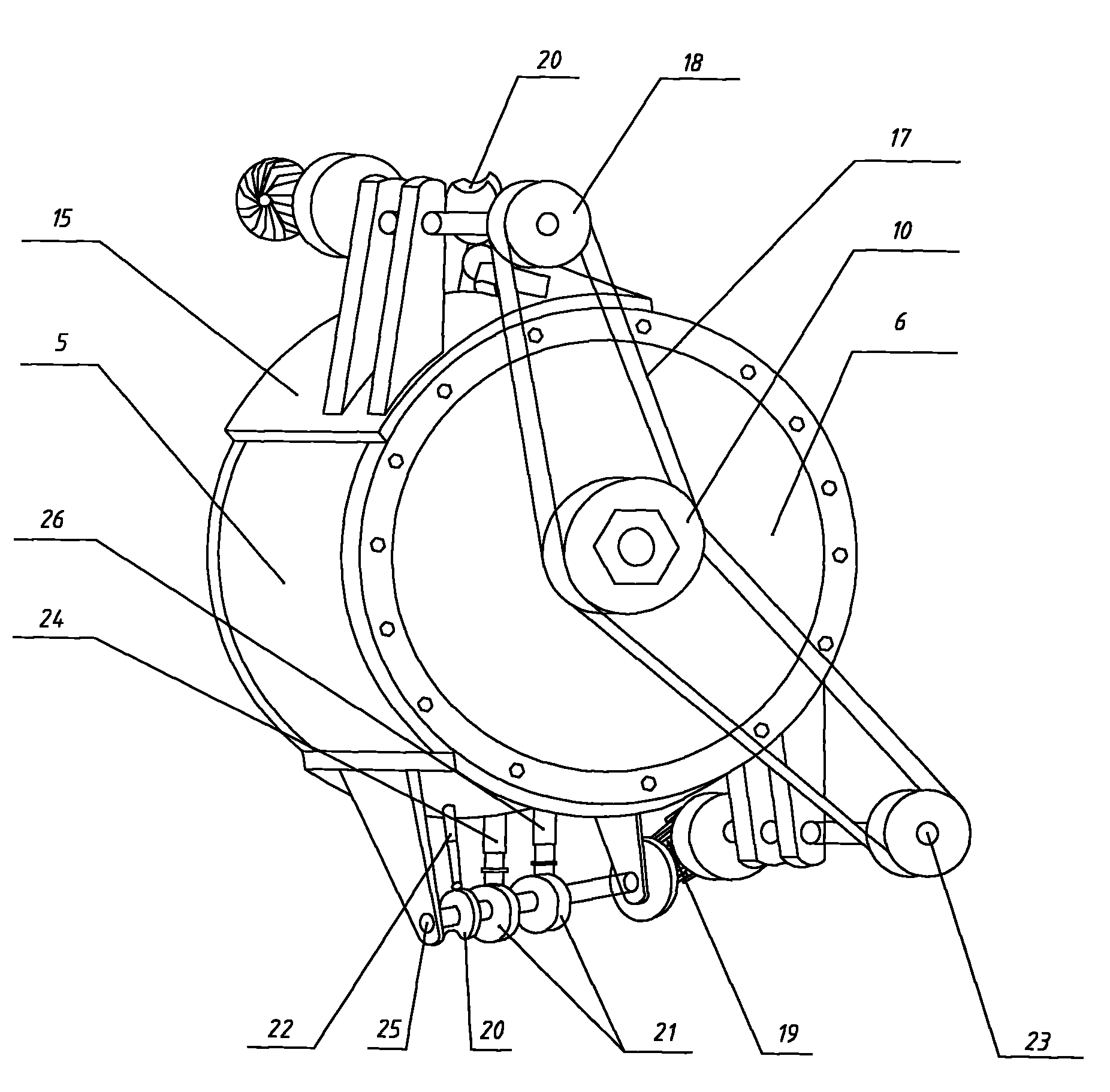
Figure 2 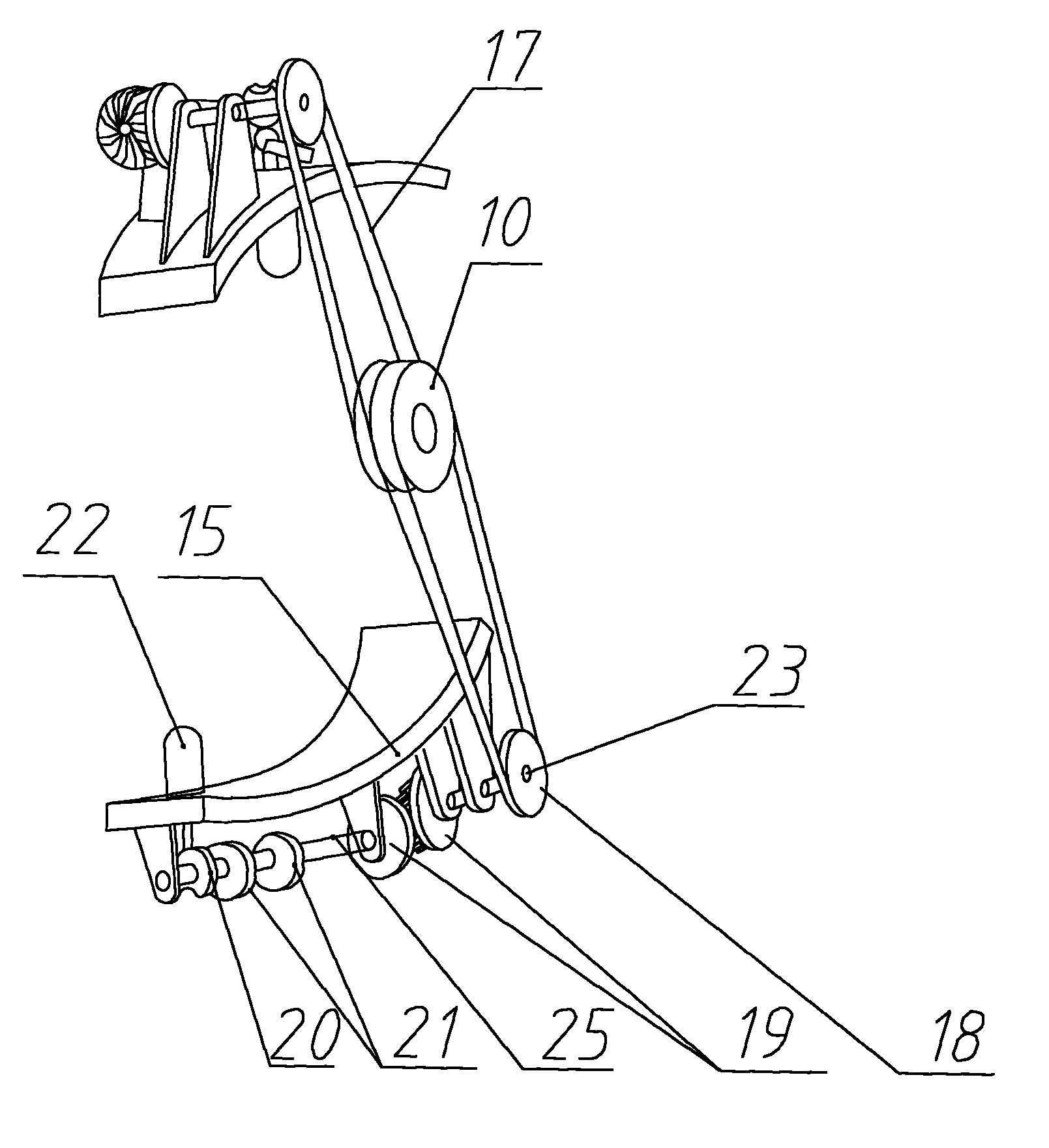
Figure 3
Abstract
Description
1. Technical field
[0001] The invention relates to an internal combustion engine, a gasoline engine and a natural gas engine, in particular to a cam mechanism in a piston circular motion internal combustion engine. 2. Technical Background
[0002] In the prior art, comparatively mature piston reciprocating internal combustion engines and rotor internal combustion engines are generally used, and its existing engines have congenital defects: 1. The piston of the existing piston linear motion internal combustion engine is a linear reciprocating motion up and down, and the piston The working stroke of the air compressor is small, and the energy generated by the expansion gas is discharged without full (work) utilization, resulting in waste. Simultaneously, the connecting rod and the crank of the piston up and down linear reciprocating internal combustion engine do not transmit the thrust generated by the expansion gas to the piston, so that the thrust is accurately and completel...
Examples
Embodiment Construction
[0019] see figure 1 , the cylinder mechanism is composed of a fixed piston cylinder mechanism 4 and a timing gear 10 on the central shaft 14 on the housing, wherein the piston cylinder mechanism 4 is composed of a circular faceplate 2 with a cylindrical piston 3 and a C-shaped ring Shaped cylinder 1 is formed, and housing is formed by the connection of cylinder outer casing 5 and internal combustion engine casing 6. In the housing, the central axis 14 is connected and positioned through the bearing 7, the spring pad 8 and the fixing bolt 9, and the circular faceplate 2 with the cylindrical piston 3 is fixed in the middle of the central axis 14, and the cylindrical piston 3 is fixed on the outer circumference of the circular faceplate 2 evenly. Distribution, at least two or more. The central shaft 14 is not only the center of the circular motion of the piston of the piston rotary internal combustion engine, but also the power output shaft of the internal combustion engine. Be...