Deep-lying storage method of carbon dioxide

A carbon dioxide and storage method technology, applied in container filling methods, gas/liquid distribution and storage, equipment loaded into pressure vessels, etc., can solve the problem of not fundamentally solving carbon dioxide emissions, so as to prevent the sea level from rising continuously, Effect of preventing global temperature rise and simple structure of the device

Inactive Publication Date: 2011-08-03
江苏恒源碳创环境技术有限公司
View PDF0 Cites 0 Cited by
  • Summary
  • Abstract
  • Description
  • Claims
  • Application Information

AI Technical Summary

Problems solved by technology

[0003] The existing recycled liquefied carbon dioxide is generally used in carbon dioxide gas shielded welding and carbonated beverages. Such a recycling method essentially still discharges carbon dioxide into the atmosphere twice, and does not fundamentally solve the problem of carbon dioxide emissions.

Method used


Image

  • Deep-lying storage method of carbon dioxide
  • Deep-lying storage method of carbon dioxide
  • Deep-lying storage method of carbon dioxide

Examples


Embodiment 1

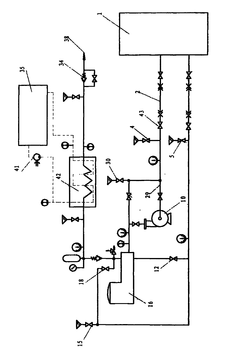
[0021] Such as figure 1 Shown, the present invention comprises the following steps:

[0022] 1) Pump the liquid-phase carbon dioxide from the tank truck or tank ship into the storage tank 1, and the output end of the carbon dioxide in the storage tank 1 is divided into gas phase and liquid phase to reach the inlet of the high-pressure pump 16, wherein the liquid phase passes through the shielded pump 10 to the inlet of the high pressure pump 16. High pressure pump 16 inlets.

[0023] 2) Liquid-phase carbon dioxide enters the high and low pressure manifolds 29 of the high pressure pump 16 and the high pressure pump 16, respectively opens the first pressure relief valve 4, the second pressure relief valve 5, and the third pressure relief valve in the high and low pressure manifolds 29 The valve 15 and the fourth pressure relief valve 30 discharge the air in the manifold 29, and the above pressure relief valve is closed for about 5-6 seconds after exhausting; The same pressure ...

Embodiment 2

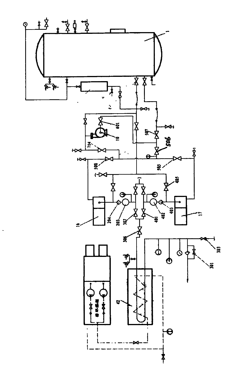
[0030] Such as figure 2 As shown, in this embodiment, two high-pressure pumps 16 and 17 are used to form a high-pressure pump group, which can accelerate the delivery speed of liquid-phase carbon dioxide. The steps of this embodiment are as follows:

[0031] 1) The output end of carbon dioxide in the storage tank 1 is divided into two paths, the gas phase and the liquid phase. After the liquid phase passes through the switching valve 507, one of the two processes can be selected to run. One path enters the canned pump 10 from the inlet valve 601, and after pressurization No. 1 high-pressure pump 16 and No. 2 high-pressure pump 17 are supplied by delivery valve 704, No. 1 pump inlet valve 500 and No. 2 pump inlet valve 505; the other one is supplied to No. 1 pump inlet valve 500 and No. No. pump inlet valve 505 inlet.

[0032] 2) The No. 1 high-pressure pump 16 and the No. 2 high-pressure pump 17 continue to raise the liquid-phase carbon dioxide to the required working press...


PUM


Abstract

The invention discloses a deep-lying storage method of carbon dioxide, which comprises the following steps of: (1) separating the output end of a carbon dioxide storage tank into two ways of a gas phase and a liquid phase reaching an inlet of a high-pressure pump; (2) enabling liquid-phase carbon dioxide to enter the high-pressure pump and a high-pressure pipe manifold and a low-pressure pipe manifold of the high-pressure pump and swiping off air in the pipe manifold so that the same pressure is established in the high-pressure pipe manifold and the low-pressure pipe manifold of the high-pressure pump as that in the carbon dioxide storage tank; (3) starting a shielding pump, carrying out low-pressure leakage to the high-pressure pipe manifold and the low-pressure pipe manifold again and establishing the output pressure of the shielding pump in normal working conditions; (4) circularly cooling the high-pressure pump; and (5) heating the liquid-phase carbon dioxide entering a heat exchanger to about 10-15 DEG C and pumping the carbon dioxide to the position of an underground sealing level by the high-pressure pump until the sealing level is saturated to affuse cement to seal a well.The invention radically solves the problem of processing carbon dioxide emission, and a device adopting the method has simple structure, compactness, lightness and low use cost so that a discarded mined or a low-yield oil well can be recycled.

Description

technical field [0001] The invention relates to a carbon dioxide emission reduction method, in particular to a liquid-phase storage and deep underground method of carbon dioxide, which belongs to the technical field of environmental protection. Background technique [0002] With the continuous growth of population and the continuous development of human industrial and agricultural production and transportation, the emission of gaseous carbon dioxide continues to increase, and the global average temperature continues to rise. If active measures to reduce carbon dioxide emissions are not taken, the global average temperature will continue to increase by 1.4°C to 5.8°C from now to 2100. At that time, Antarctica’s glaciers will melt faster, and sea levels will continue to rise, threatening the survival of many island countries in the Pacific Ocean and the Indian Ocean. Safe, and lead to the prevalence and spread of some diseases related to warm climates such as malaria and dengu...

Claims


Application Information

Patent Timeline
Patent Type & Authority Patents(China)
IPC IPC(8): F17C5/06
Inventor 沈少锋毛恒松
Owner 江苏恒源碳创环境技术有限公司
Why Eureka
Try Eureka