
Choke

A technology of chokes and plate-shaped objects, which is applied in the direction of transformer/inductor magnetic core, inductor/transformer/magnet manufacturing, electrical components, etc., which can solve the problems of unautomated production, high labor cost, and consumption

Inactive Publication Date: 2010-07-28
CYNTEC
View PDF0 Cites 17 Cited by
  • Summary
  • Abstract
  • Description
  • Claims
  • Application Information

AI Technical Summary

Problems solved by technology

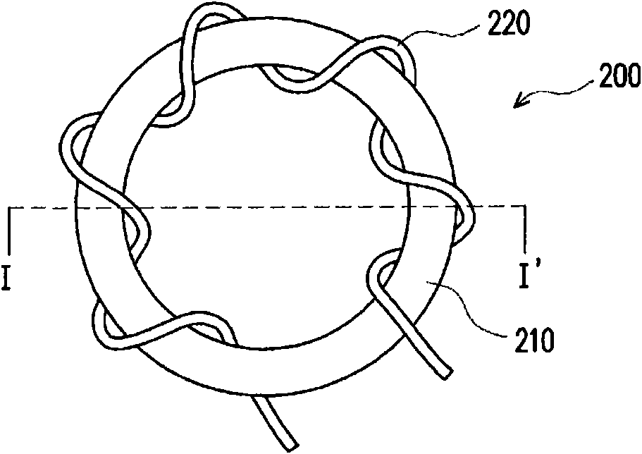
However, the choke 200 needs to manually wind the wire 220 on the annular magnetic core 210, and cannot be produced in an automated manner. Therefore, the manufacturing process of the choke 200 requires considerable labor costs.

Method used


Image

  • Choke
  • Choke
  • Choke

Examples


Embodiment Construction

[0038] image 3 It is a cross-sectional view of a choke according to an embodiment of the present invention. Please refer to image 3 , the choke 300 of this embodiment includes a drum core 310 and a wire 320 . The drum-shaped magnetic core 310 includes a central column 312, a first plate-shaped body 314 and a second plate-shaped body 316, and the two ends of the central column 312 are respectively connected to the first plate-shaped body 314 and the second plate-shaped body 316 . The material of the drum-shaped magnetic core 310 is a ferrous alloy, and the ferrous alloy can be an iron-silicon aluminum alloy, an iron-nickel-molybdenum alloy, an iron-nickel alloy, or an amorphous (Amorous) alloy. The drum-shaped magnetic core 310 is formed by powder molding and then sintered at a temperature above 300° C., and a preferred sintering temperature is above 600° C. The magnetic permeability u (Permeability) of the drum core 310 is, for example, 60-300, preferably 60-125. The ma...


PUM

PropertyMeasurementUnit
thicknessaaaaaaaaaa
thicknessaaaaaaaaaa
heightaaaaaaaaaa

Abstract

The invention discloses a choke which comprises a drum-type magnetic core and at least one lead. The drum-type magnetic core comprise a middle column, a first tabular body and a second tabular body, both ends of the middle column are respectively connected with the first tabular body and the second tabular body, the drum-type magnetic core is made of an iron-contained alloy, and the lead is provided with a winding part wound around the middle column.

Description

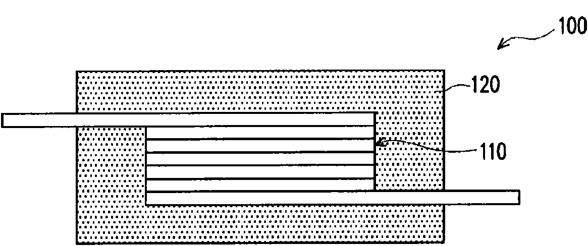
technical field [0001] The present invention relates to a choke, and in particular to a choke with low magnetic core energy loss. Background technique [0002] The function of the choke is to stabilize the current in the circuit and achieve the effect of filtering noise. The function is similar to that of a capacitor. It also stores and releases the electric energy in the circuit to adjust the stability of the current. Compared with the capacitor, the electric field ( charge) to store electrical energy, and the choke is achieved in the form of a magnetic field. In the application of the choke, there will be energy loss of the wire (commonly called copper loss, copper wire loss) and energy loss of the magnetic core (commonly called iron loss, core loss). [0003] figure 1 It is a sectional view of an existing choke. Please refer to figure 1 , the existing choke 100 is usually used in electronic products requiring high saturation current, such as a DC-DC Converter of a not...

Claims


Application Information

Patent Timeline
Patent Type & Authority Applications(China)
IPC IPC(8): H01F17/04H01F27/24H01F41/02B22F3/12
Inventor 黄逸珉谢明家谢蓝青吴宗展
Owner CYNTEC
Learn More