Hand drier

A hand-drying, slender-hole technology, applied to household appliances and other directions, can solve the problems of poor drying, poor drying efficiency, and detrimental feeling of use, etc., and achieve the effect of strong drying, improving drying and good feeling of use.

Active Publication Date: 2010-08-04
MITSUBISHI ELECTRIC CORP
View PDF1 Cites 5 Cited by
  • Summary
  • Abstract
  • Description
  • Claims
  • Application Information

AI Technical Summary

Problems solved by technology

[0006] In Patent Document 1, although the turbulent flow due to the collision between the jets can be reduced, since the circular jet whose drying efficiency is wors

Method used


Image

  • Hand drier
  • Hand drier
  • Hand drier

Examples


Example Embodiment

[0029] Hereinafter, embodiment of the hand dryer of this invention is described in detail based on drawing. In addition, this invention is not limited to this embodiment.

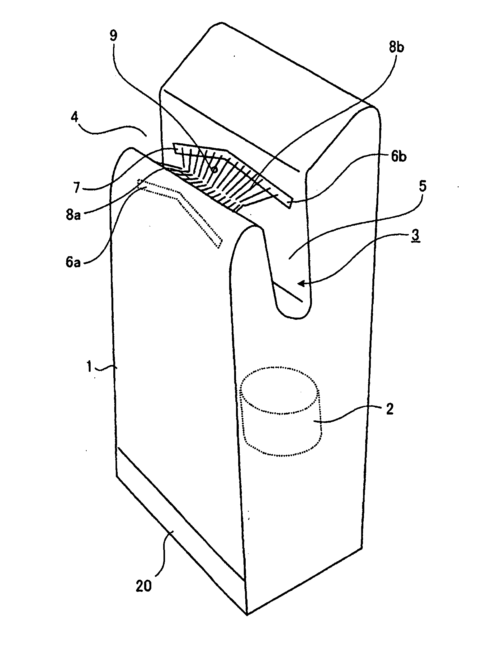
[0030] use Figure 1 to Figure 10 Embodiments of the present invention will be described. figure 1 It is a figure which shows the external appearance structure of the hand dryer which concerns on this embodiment. like figure 1 As shown, the hand drying device has a main body box 1 which constitutes a housing with a hand insertion portion 3 at the top. On the upper side of the main body case 1 is formed a hand insertion portion 3 as a concave space constituted by a hand insertion opening 4 and a drying treatment space 5 connected to the hand insertion opening. The hand insertion part 3 has both sides open to form a deep-bottomed inclined open groove that can be inserted and withdrawn by the hand, and can be inserted and withdrawn obliquely up and down while both hands are aligned in the plane.

[0031] ...


PUM


Abstract

The invention discloses a hand drier. The hand drier comprises a box body (1), a high-pressure air flow generator (2) and air nozzle parts (6a, 6b) oppositely arranged on a front side and a back side, wherein a concave hand insertion part (3) is formed on the box body (1); the high-pressure air flow generator (2) is internally arranged inside the box body (1) generating high-pressure air flow; the air nozzle parts (6a, 6b) oppositely arranged on the front side and the back side spray the high-pressure air flow generated by the high-pressure air flow generator (2) to the hand insertion part (3) and are formed by a plurality of linear slit-shaped nozzles (7), so that the lengths and/or the setting intervals of the slit-shaped nozzles (7) are different on the front side and the back side. The hand drier has the advantages of noise prevention, high drying efficiency, good handfeel, and no complex structure.

Description

[0001] This application is a divisional application of the application of Mitsubishi Electric Corporation on August 18, 2005 with the title of invention "hand drying device" and application number 200580001769.4. technical field [0002] The present invention relates to a hand drying device for hygienically drying wet hands after washing by spraying high-speed airflow. Background technique [0003] The hand drying device that has been developed is a hygienic hand drying process that blows off moisture and dries the wet hands after washing without wiping with a towel or handkerchief, etc., by jetting high-speed air. Such a device utilizes the kinetic energy of high-speed airflow to blow off moisture adhering to hands, and therefore has problems of turbulence and noise due to collisions between opposing jets. [0004] Therefore, in Patent Document 1, the nozzle on one side is formed as a slit discharge hole, and the opposite nozzle forms a structure in which the circular disch...

Claims


Application Information

Patent Timeline
IPC IPC(8): A47K10/48
Inventor 龟石圭司小林章树中村淳
Owner MITSUBISHI ELECTRIC CORP
Why Eureka
Try Eureka