Clamping body for tool box

A technology of tool boxes and clamping bodies, applied in the field of tool boxes, can solve problems such as difficulty in inserting and pulling out tools, difficulty in determining the tightness of the socket and tool handle, etc., to reduce friction, reduce contact area, and reduce force. small effect

Inactive Publication Date: 2010-08-04
吴克军
View PDF1 Cites 2 Cited by
  • Summary
  • Abstract
  • Description
  • Claims
  • Application Information

AI Technical Summary

Problems solved by technology

[0003] The present invention overcomes the defect that the fit between the socket of the tool box and the handle of the tool is not easy to determine, and the tool is difficult to insert and pull out in the prior art, and provides a clamping body for the tool box. Robust tooling, easy tool insertion or extraction

Method used


Image

  • Clamping body for tool box
  • Clamping body for tool box
  • Clamping body for tool box

Examples


Embodiment

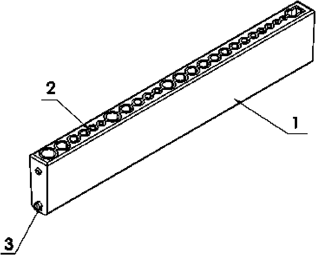
[0024] Example: such as figure 1 As shown, a holding body for a tool box includes a housing 1 , a holding body 2 fixed in the housing and provided with an insertion hole, and pivots 3 are provided at both ends of the housing.

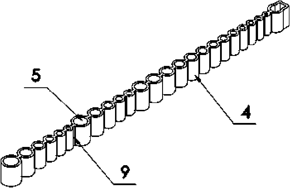
[0025] The holding body 2 is composed of 25 cylinders and 4 conjoined bodies, the cylinders are provided with jacks 5, and the cylinders are connected with ribs 9, such as figure 2 shown.

[0026] The lower end of the jack 5 is provided with uniformly distributed four ribs 6, the ribs are in the shape of a triangular pyramid, the height of the triangular pyramid is 15mm, and the length of the triangle at the bottom of the triangular pyramid is 3mm, as Figure 4 shown.

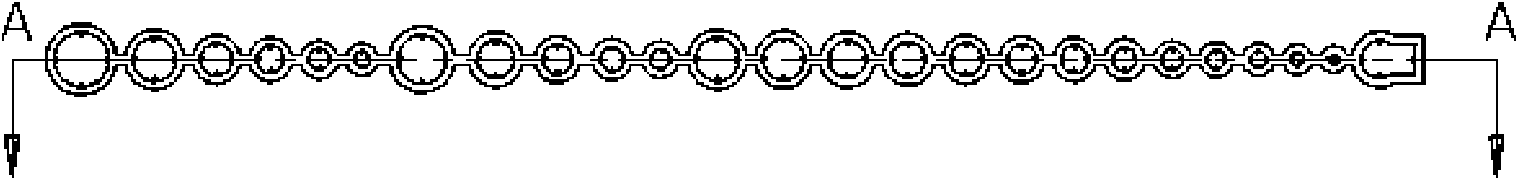
[0027] like Figure 5 As shown, the housing 1 is a cuboid with an opening 7 on one side, and the opening is used to accommodate the elastic holding body 2. The opening of the housing is provided with an inwardly folded edge 8, which is pressed into the housing by elastic deformation....

Embodiment 2

[0029] Embodiment 2: as Figure 7 As shown, the holding body is a cuboid structure 11, and the side walls of the socket 5 provided thereon are evenly provided with four ribs in the shape of a trapezoidal quadrangular prism, and the upper ends of the ribs are arranged toward the center of the jack. There is an inclined plane, and twenty-four round holes 5 and a special-shaped jack 9 are set on the cuboid 11.

[0030] In the present invention, ribs are arranged in the socket of the holding body to eliminate the closed air film inside the socket, avoid the negative pressure of the air film when the tool is pulled out, reduce the contact area between the tool and the wall of the socket, reduce friction, and avoid The soft material on the wall of the socket rebounds and tightly wraps the tool handle, making it difficult to pull out the tool due to the large static friction force; because the force of inserting or pulling the tool is greatly reduced, the relevant parts, especially t...


PUM


Abstract

The invention discloses a clamping body for a tool box, aiming at overcoming the defects that the clamping body of the tool box in the prior art is difficult to plug and pull tools and providing a tool clamping body with reliable clamping and easy plugging and pulling. The points are as follows: the clamping body comprises a shell, and a holding body which is fixed in the shell and is provided with a plurality of jacks; the jacks of the holding body is internally provided with a plurality of raised rib blocks which can be ribs with strip structures or rib granules with granular structures; and the rib blocks and the holding body are in a connected structure. The clamping body is provided with the rib blocks in the jacks of the holding body, thus eliminating closed air films at the walls of the jacks, reducing the contact area of the tool and the walls of the jacks, and avoiding the phenomenon that soft materials of the walls of the jacks rebound and wrap a tool handle to lead the tool with ultra-large static friction to be difficultly pulled; and since the acting force of plugging or pulling the tool is greatly reduced, the service life of the clamping body and the whole tool box can be prolonged.

Description

technical field [0001] The invention relates to a tool box, in particular to a clamping body for clamping a rod-shaped tool in the tool box. Background technique [0002] Most of the existing tool boxes for placing rod-shaped tools are cuboid-shaped boxes, and the tools such as drill bits and taps are thrown into the box to complete the job. This scattered storage method adds trouble to finding tools when they are used again. It also causes the collision between the tools to cause damage to the cutting edge. The innovative solution, such as the Chinese patent number ZL200520027433.2, is named tool box structure, which includes a bottom box body with accommodating space. A storage component and a cover are rotatably connected. One end of the storage component is concavely provided with several sockets, and a vertically adjacent end surface is horizontally arranged with a penetrating shaft perpendicular to the socket, through which a rotary rod for clamping structure is insert...

Claims


Application Information

Patent Timeline
Patent Type & Authority Applications(China)
IPC IPC(8): B25H3/02
Inventor 吴克军
Owner 吴克军
Why Eureka
Try Eureka