Movable-molding cavity injection-pressing moulding method of plastic microfluidic chip

A technology of microfluidic chip and molding method, applied in the direction of coating, etc., can solve the problem of not copying the right angle of the root of the mold cavity insert, and achieve the effect of avoiding spraying

Inactive Publication Date: 2010-08-04
DALIAN UNIV OF TECH
View PDF0 Cites 6 Cited by
  • Summary
  • Abstract
  • Description
  • Claims
  • Application Information

AI Technical Summary

Problems solved by technology

[0002] The current plastic microfluidic chip injection molding method, for plastic microfluidic chips that require a rectangular cross-sectional shape of the

Method used


Image

  • Movable-molding cavity injection-pressing moulding method of plastic microfluidic chip
  • Movable-molding cavity injection-pressing moulding method of plastic microfluidic chip
  • Movable-molding cavity injection-pressing moulding method of plastic microfluidic chip

Examples


Embodiment Construction

[0020] The specific embodiments of the present invention will be described in detail below in conjunction with the technical solutions and accompanying drawings.

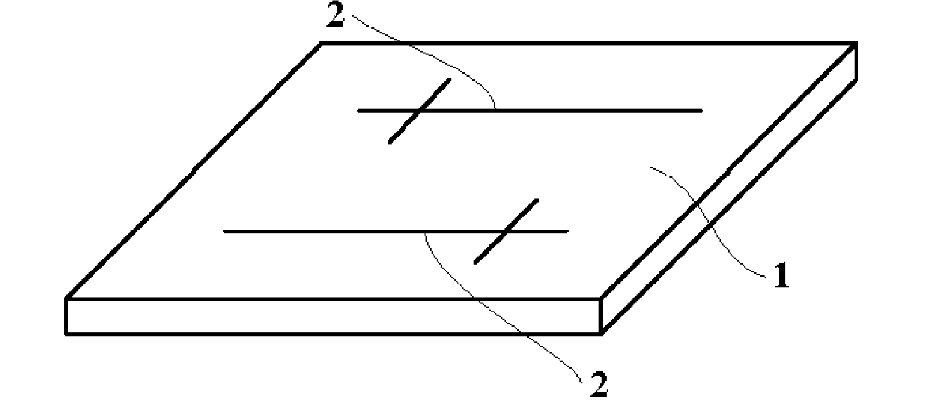
[0021] Such as figure 1 As shown, the plastic microfluidic chip 1 to be molded has microgrooves 2 . The dimensions of the plastic microfluidic chip 1 are: length 40mm-100mm, width 25mm-100mm, thickness 1mm-2mm. The microgroove 2 can be as figure 1 A cruciform arrangement is shown, but a serpentine or other arrangement is also possible. The molding material of the plastic microfluidic chip 1 can be polymethyl methacrylate (PMMA) or polycarbonate (PC).

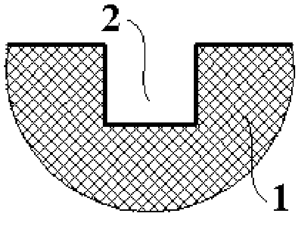
[0022] Such as figure 2 As shown, the cross-sectional shape of the microgroove 2 on the plastic microfluidic chip 1 is required to be rectangular, trapezoidal or triangular. The cross-sectional size of the micro-groove 2 is: a width of 30 microns to 100 microns, and a height of 30 microns to 100 microns.

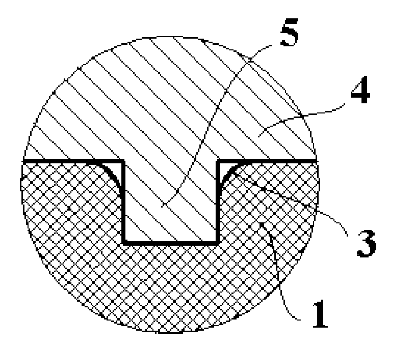
[0023] Such as image 3 As shown, the microgrooves 2 o...


PUM


Abstract

The invention discloses a movable-moulding cavity injection-pressing moulding method of a plastic microfluidic chip, which belongs to the technical field of polymer material moulding, and is characterized in that: a plastic melt is injected after a mould is closed completely, a mould cavity insert moves backward under an injecting pressure to enlarge the mould cavity gradually; after injection is finished, the mould cavity insert is moved forwards by a wedge to press a plastic part in the mould cavity compactly and copy the cross section profile of the micro embossments of the mould cavity insert onto the surface of the plastic microfluidic chip completely; and after the mould is opened and the plastic microfluidic chip is taken out, the wedge is withdrawn to ensure that the backward movement of the mould cavity insert in a next production period is unconstrained. The method comprises the steps of mould closing, injection, pressing, mould opening, finished product collecting and wedge withdrawing in turn. The method has the advantages of realizing the injection-pressing moulding of the plastic microfluidic chip on a common plastic injection moulding machine, avoiding jetting in the injection process, and ensuring that the micro channels on the moulded plastic microfluidic chip have the same cross section profile as the micro embossments of the mould cavity insert.

Description

technical field [0001] The invention belongs to the technical field of polymer material molding, and relates to a cavity-moving injection molding method for a plastic microfluidic chip. Background technique [0002] The current plastic microfluidic chip injection molding method, for plastic microfluidic chips that require a rectangular cross-sectional shape of the microgroove, it is easy to make rounded corners at the opening of the microgroove without replicating the mold cavity insert Slightly raised root at right angles. Contents of the invention [0003] The technical problem to be solved by the present invention is to provide a cavity mobile injection molding method for plastic microfluidic chips, so that the microgrooves of the plastic microfluidic chips have micro-protrusion roots at the openings that match the mold cavity inserts. same outline. [0004] The technical solution of the present invention is: the upper surface of the cavity insert has micro-protrusion...

Claims


Application Information

Patent Timeline
IPC IPC(8): B29C45/14
Inventor 祝铁丽王学虎王敏杰于同敏宋满仓刘莹刘克成
Owner DALIAN UNIV OF TECH
Why Eureka
Try Eureka