Pneumatic conveyer

A technology of pneumatic conveying and conveying pipelines, which is applied in the direction of conveying bulk materials, conveyors, transportation and packaging, etc., which can solve the problems of difficult to meet the needs of conveying materials, unfavorable solid-gas mixture, unfavorable discharge speed, etc., and achieve high work efficiency. Efficiency, maintenance of reliability, effect of reducing clogging

Active Publication Date: 2010-08-04
FUJIAN LONGKING
View PDF6 Cites 31 Cited by
  • Summary
  • Abstract
  • Description
  • Claims
  • Application Information

AI Technical Summary

Problems solved by technology

Since the sealing performance of the soft-sealed valve depends on the air supply of the air source, and the sealing ring must be released first when it is opened, the pneumatic conveying device using this valve cannot carry out material transportation after the material is fully fluidized. It is not conducive to the formation of a uniform solid-gas mixture, it is not conducive to the precise control of the discharge speed, and it is difficult to meet the needs of the current conveying materials

Method used


Image

  • Pneumatic conveyer
  • Pneumatic conveyer

Examples


Embodiment 1

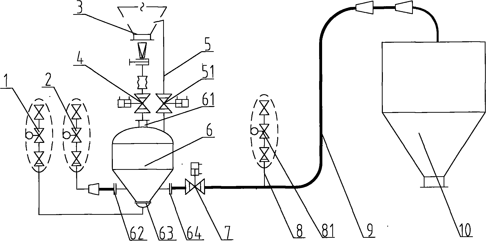
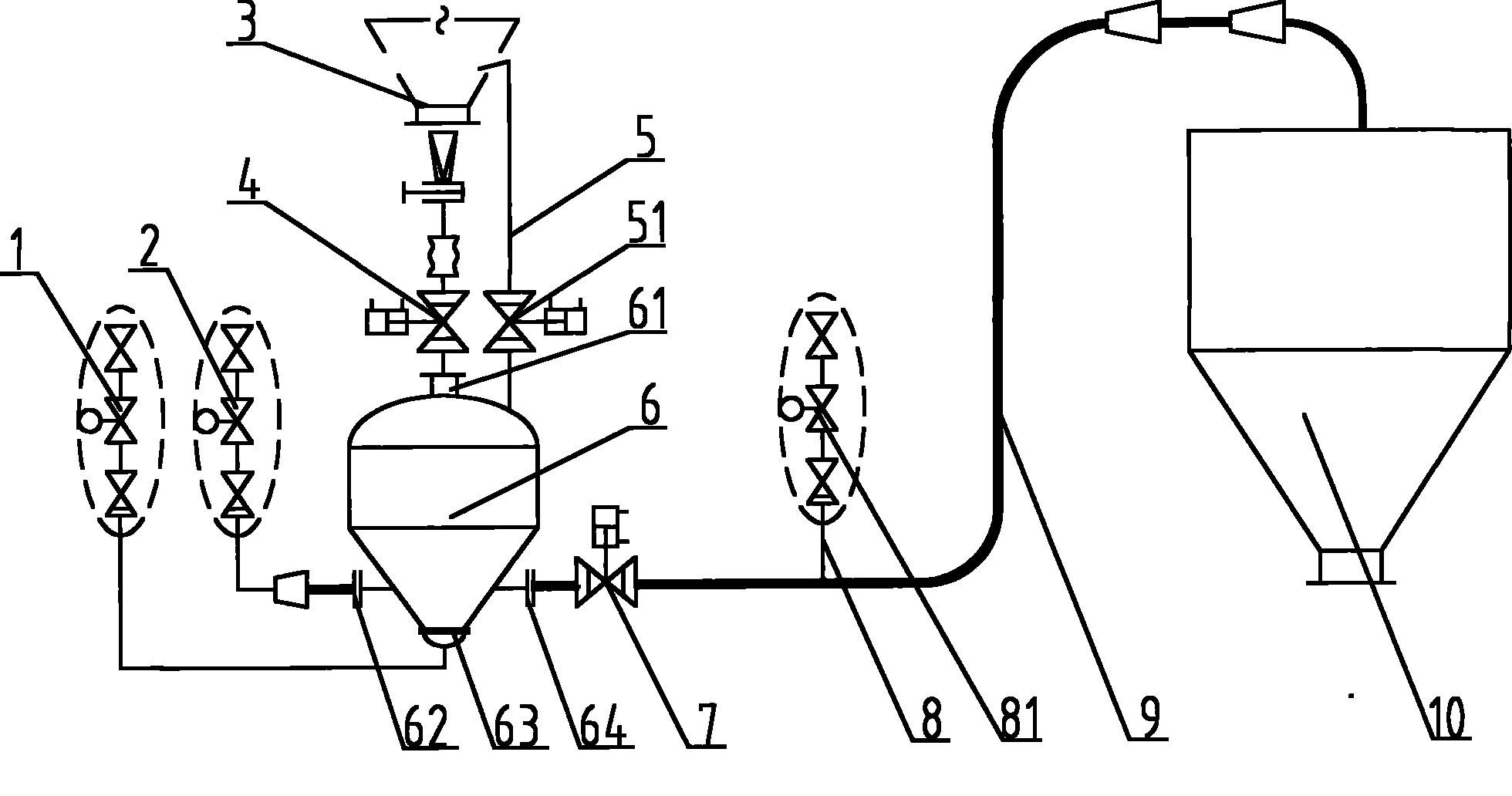
[0034] The pneumatic conveying device provided in Embodiment 1 includes a bin pump 6 , a conveying pipeline 9 and an air supply pipeline 8 . Wherein, the warehouse pump 6 has a material inlet 61 , a driving air inlet 62 , a fluidization air inlet 63 and a material outlet 64 .

[0035]The material to be transported stored in the initial bin 3 can reach the bin pump 6 through the feed port 61 . In this example, the warehouse pump 6 is located below the initial warehouse 3, and the feed port 61 is opposite to the discharge port of the initial warehouse 3, and the two are connected through the feed valve 4, and the opening and closing of the feed valve 4 can be controlled. The communication state between the initial bin 3 and the bin pump 6, so as to realize the control of the feed. The benefit of the location of the bin pump 6 below the initial bin 3 is that the material can flow into the bin pump 6 smoothly through the feed port 61 by utilizing the action of gravity. In order ...


PUM


Abstract

The invention discloses a pneumatic conveying device, which comprises a bin pump and a delivery duct. The driving air inlet of the bin pump is connected with a bin pump cone and is in the same central line with the discharging hole of the bin pump. The diameter of the delivery duct is increased gradually. The device also comprises at least one air make-up duct. The air make-up duct is provided with a plurality of openings circumferentially distributed along the inner wall of the delivery duct. The opening direction is consistent with the flowing direction of a solid-gas mixture. The working process comprises three steps, namely feeding, fluidifying and adjusting the flow rate of the solid-gas mixture. Air is introduced into the delivery duct by the air make-up duct to adjust pressure in the delivery duct and adjust the flow velocity of solid-gas mixture so as to ensure that the solid-gas mixture has proper flow velocity, thus lowering the wear rate of the delivery duct, reducing the possibility of delivery duct blockage, and ensuring the working reliability of the pneumatic conveyer.

Description

technical field [0001] The invention relates to a technique for conveying materials by gas power, in particular to a pneumatic conveying device. Background technique [0002] Generally speaking, a pneumatic conveying device includes an air source, a warehouse pump and a conveying pipeline. Wherein, the gas source is used to provide gas source power for the chamber pump, so that the gas enters the chamber pump at a predetermined flow rate and flow rate, and establishes a predetermined pressure in the chamber pump. The warehouse pump is the core part of the pneumatic conveying device. On the one hand, it receives the predetermined materials to be transported, and on the other hand, it organizes the air flow reasonably, so that the received materials are mixed with the gas to form a solid-gas mixture. The formed solid-gas mixture is in the warehouse pump. Flow outward under the action of internal pressure. The conveying pipeline is connected between the outlet of the warehous...

Claims


Application Information

Patent Timeline
Patent Type & Authority Applications(China)
IPC IPC(8): B65G53/16B65G53/52B65G53/46B65G53/58B65G53/60
Inventor 潘仁湖邱生祥曹强利江兴涛张进明田青袁礼
Owner FUJIAN LONGKING
Why Eureka
Try Eureka