

Measuring system and measuring method of mass, center of mass and moment of inertia of rigid body
A moment of inertia and measurement system technology, which is applied in the field of measurement, can solve problems such as cycle lengthening, measurement cycle error, and poor accuracy of moment of inertia, and achieve the effects of easy installation and disassembly, removal of accidental errors, and high action accuracy
- Summary
- Abstract
- Description
- Claims
- Application Information
AI Technical Summary
Problems solved by technology
Method used
Image

Examples
Embodiment Construction
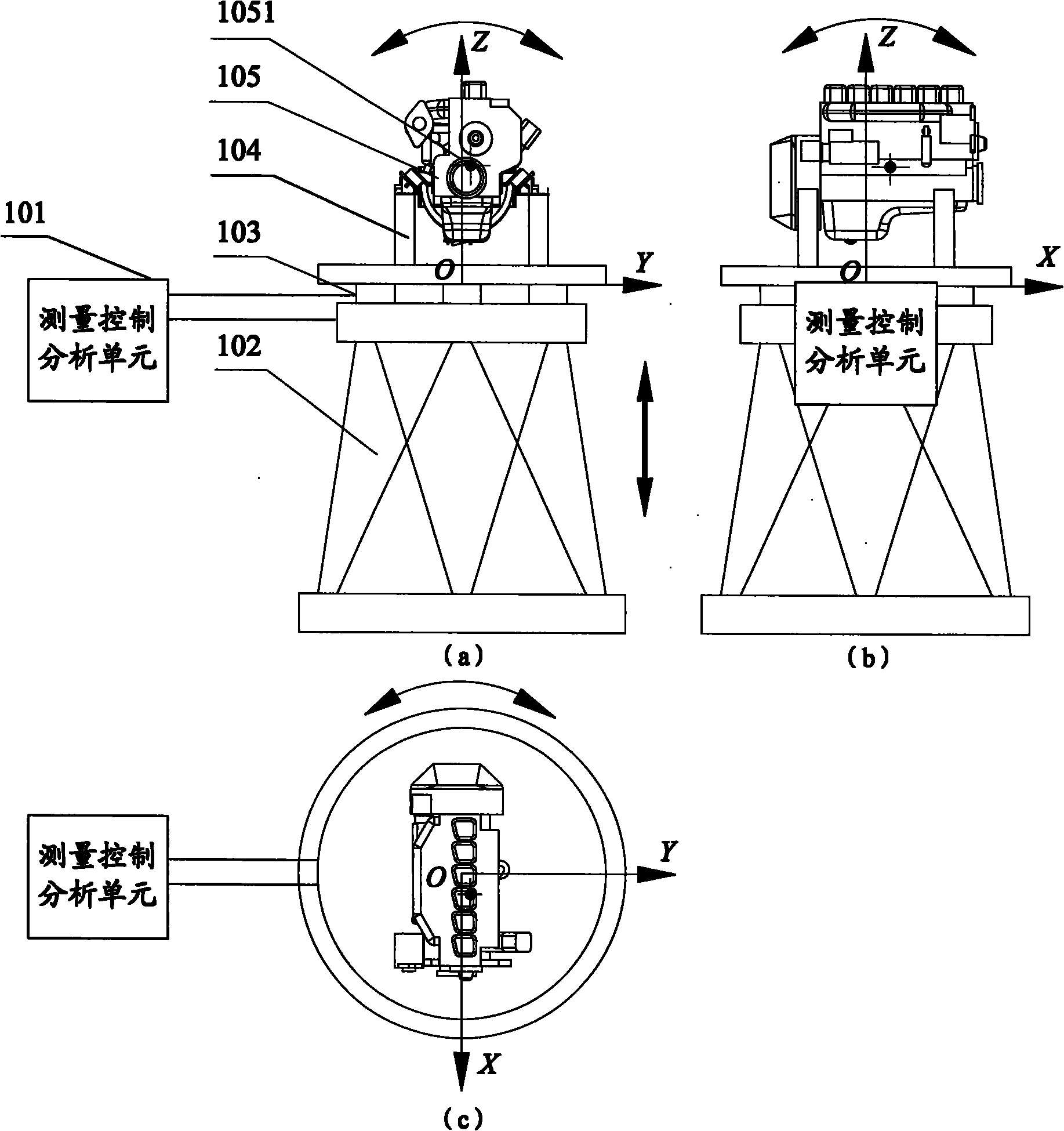
[0046]In order to make the above objects, features and advantages of the present invention more comprehensible, the present invention will be further described in detail below in conjunction with the accompanying drawings and specific embodiments.
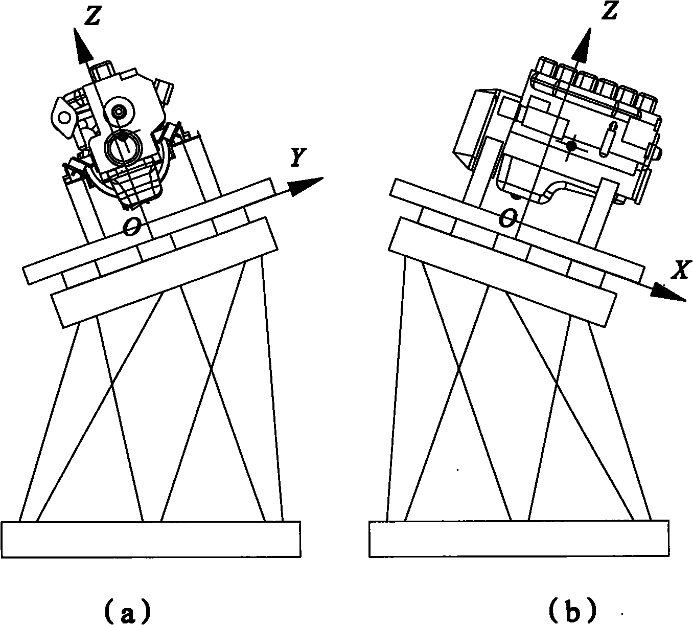
[0047] refer to figure 1 , which shows a structural schematic diagram of an embodiment of a measurement system for the mass, center of mass and moment of inertia of a rigid body of the present invention, wherein the measurement system includes:
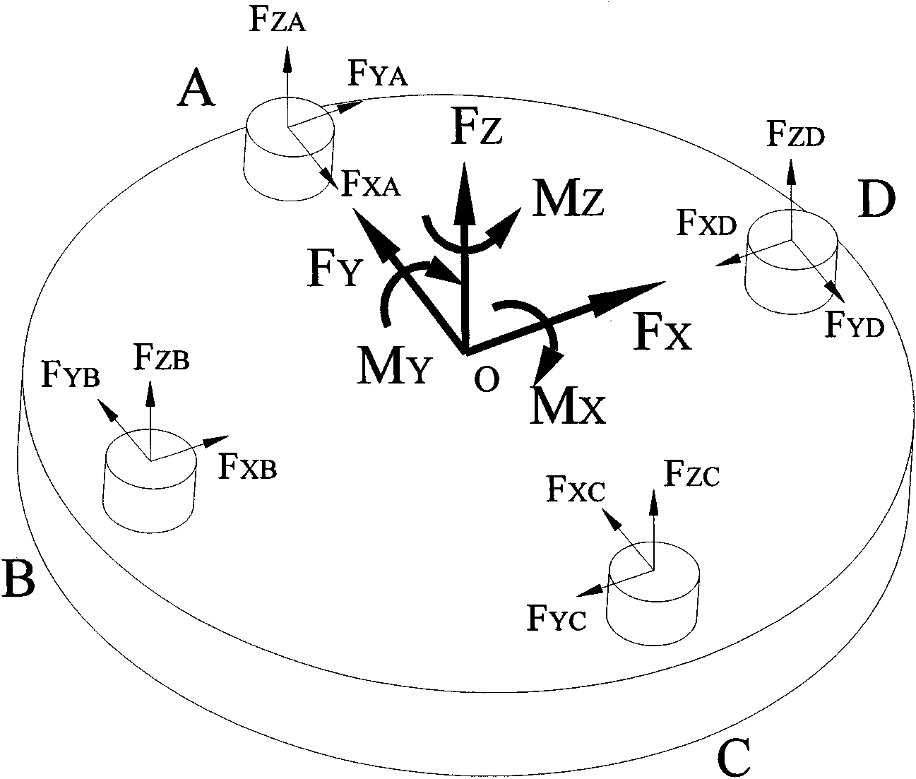
[0048] The measurement control analysis unit 101 is used to control the posture or motion mode of the six-degree-of-freedom motion platform by sending motion signals, and analyze and calculate the measured rigid body according to the motion signals and the force and torque transmitted by the six-component force sensor. 105 mass, center of mass and moment of inertia;
[0049] The six-degree-of-freedom motion platform 102 is used to move according to the corresponding posture or motion mode...
PUM
 Abstract
Description
Claims
Application Information